Flap drive system

Active Publication Date: 2011-09-06
JULIUS BLUM GMBH
View PDF27 Cites 14 Cited by
  • Summary
  • Abstract
  • Description
  • Claims
  • Application Information

AI Technical Summary

Benefits of technology

[0016]If provision is made for the electric drive to have a gear mechanism, provision may furthermore be made for the interface to be coupled to the gear mechanism on the side of the electric drive. This embodiment affords the advantage that no modification of pre-existing mechanical actuating units is required, provided that the units have an interface.
[0017]In a further preferred embodiment of the invention, a coupling can be connected between the at least one electric motor and the interface or between the at least one electric motor and the gear mechanism.
[0018]The coupling can be embodied, for example, in a mechanically flexible manner (for example as a hose coupling). A mechanically flexible embodiment of this type of the coupling helps to reduce transmission of the drive noise of the electric motor to the gear mechanism and if appropriate the housing part in which the gear mechanism is arranged. This is important to the extent that preferably the electric motor is mounted in a floating manner in the housing of the electric drive and therefore itself gives off hardly any vibrations to the housing. The acoustic properties of the electric drive may be further improved if provision is made for additional weights to be connected to the at least one electric motor. This allows the ratio between the s

Problems solved by technology

In other words, it is not possible to retrofit a mechanical actuating unit, which ha

Method used


Image

  • Flap drive system
  • Flap drive system
  • Flap drive system

Examples


Example

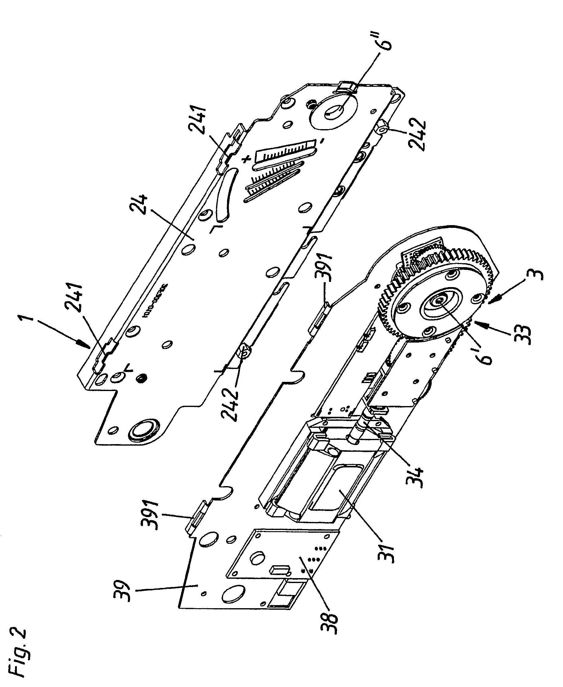
[0032]FIGS. 2 to 5 show a first exemplary embodiment of a flap drive system 1 according to the invention.

[0033]FIG. 2 shows in this case a covering surface (covering plate) 24 of a mechanical actuating unit 2 (which is not shown in greater detail in FIG. 2). The covering surface 24 has two projections 241 which serve to suspend (support) the base plate 39 of the electric drive 3. The suspending is carried out in this case via tabs 391. Once the suspending has been carried out, the electric drive 3 and the mechanical actuating unit 2 can be screwed to each other via screws (see FIG. 5), the covering surface 24 having in this exemplary embodiment appropriate receptacles 242 for the screws. FIG. 2 also shows the gear mechanism 33, the electric motor 31 and also a coupling 34 (which is in this exemplary embodiment embodied in a mechanically flexible manner) joining these two components together. A printed circuit board 38, which comprises the circuits of an open or closed-loop control u...


PUM


Abstract

A flap drive system for moving a flap mounted in a movable manner on the body of a piece of furniture has a mechanical actuating unit with an actuating arm that can be linked to the flap, and has an energy accumulator that can apply a force to the actuating arm. The flap drive system also has an electric drive secured to the actuating unit for driving the flap. The electric drive has at least one electric motor and is designed as a self-contained component, such that the electric drive can be secured to the actuating unit even when the actuating unit is already mounted on the body of the piece of furniture.

Description

[0001]This application is a Continuation of International application No. PCT / AT2008 / 000153, filed Apr. 25, 2008.BACKGROUND OF THE INVENTION[0002]The present invention relates to a flap drive system for a flap mounted in a movable manner on the body of a piece of furniture.[0003]WO 2006 / 099645 A1 discloses a flap mounted in a movable manner on the body of a piece of furniture with a mechanical actuating unit having an actuating arm which can be connected to the flap and an energy accumulator which acts on the actuating arm. Furthermore, an electric motor for driving the flap is provided as an integral component of the mechanical actuating unit. A flap drive system with constructional units or components which are closed off from one another is not disclosed.[0004]FIG. 1 shows a mechanical actuating unit according to the prior art which is mounted on the body 8 of a piece of furniture via a base plate 9. The mechanical actuating unit has in this case an energy accumulator 13 for acti...

Claims


Application Information

Patent Timeline
IPC IPC(8): A47B95/00
CPCE05D15/401E05F15/63E05F1/1058E05Y2201/22E05Y2800/205E05Y2800/232E05Y2800/238E05Y2800/70E05Y2900/20E05Y2600/51E05Y2600/528E05Y2600/56E05Y2600/626E05Y2201/232E05Y2800/11E05F15/40E05D15/46
Inventor MATTLE, KLAUS
Owner JULIUS BLUM GMBH
Why Eureka
Try Eureka