Method of manufacturing at least one projecting section of nozzle plate, nozzle plate, inkjet head and image forming apparatus

a technology of nozzle plate and projecting section, which is applied in the direction of coating, pretreatment surface, printing, etc., can solve the problems of complex manufacturing process, labor-intensive, and difficult to replace the metal plate bonded to the surface of the head substrate, so as to achieve easy repair and restoration

Inactive Publication Date: 2011-09-06
FUJIFILM CORP
View PDF3 Cites 35 Cited by
  • Summary
  • Abstract
  • Description
  • Claims
  • Application Information

AI Technical Summary

Benefits of technology

[0008]The present invention has been contrived in view of these circumstances, an object thereof being to provide a method of manufacturing at least one projecting section in a nozzle plate which is easy to manufacture and which can be restored even if damage has occurred due to a paper jam, or the like, and an object being to provide, in combination with this, a nozzle plate obtained by this method of manufacture, and an inkjet head and an image forming apparatus using same.
[0012]According to the present invention, in comparison with a related art method, it is possible to form at least one projecting section (at least one step section) in a simple and inexpensive fashion, so that repair and restoration can be carried out easily in the event of damage to the projecting section.

Problems solved by technology

However, the structure disclosed in Japanese Patent Application Publication No. 4-234665 has a drawback in that it requires labor in order to form a metal plate having holes which correspond to the nozzles.
Furthermore, it is also necessary to accurately position and bond the metal plate to the nozzles formed in the substrate, and therefore the manufacturing process is complicated.
Moreover, if mechanical damage has occurred in the metal plate due to a paper jam, or the like, then it is necessary to replace or repair (restore) the metal plate, but replacement of the metal plate bonded to the surface of the head substrate is extremely complex and hence repair and replacement is not possible in practical terms.

Method used


Image

  • Method of manufacturing at least one projecting section of nozzle plate, nozzle plate, inkjet head and image forming apparatus
  • Method of manufacturing at least one projecting section of nozzle plate, nozzle plate, inkjet head and image forming apparatus
  • Method of manufacturing at least one projecting section of nozzle plate, nozzle plate, inkjet head and image forming apparatus

Examples


first embodiment

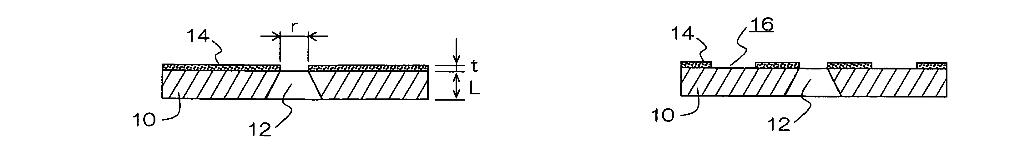
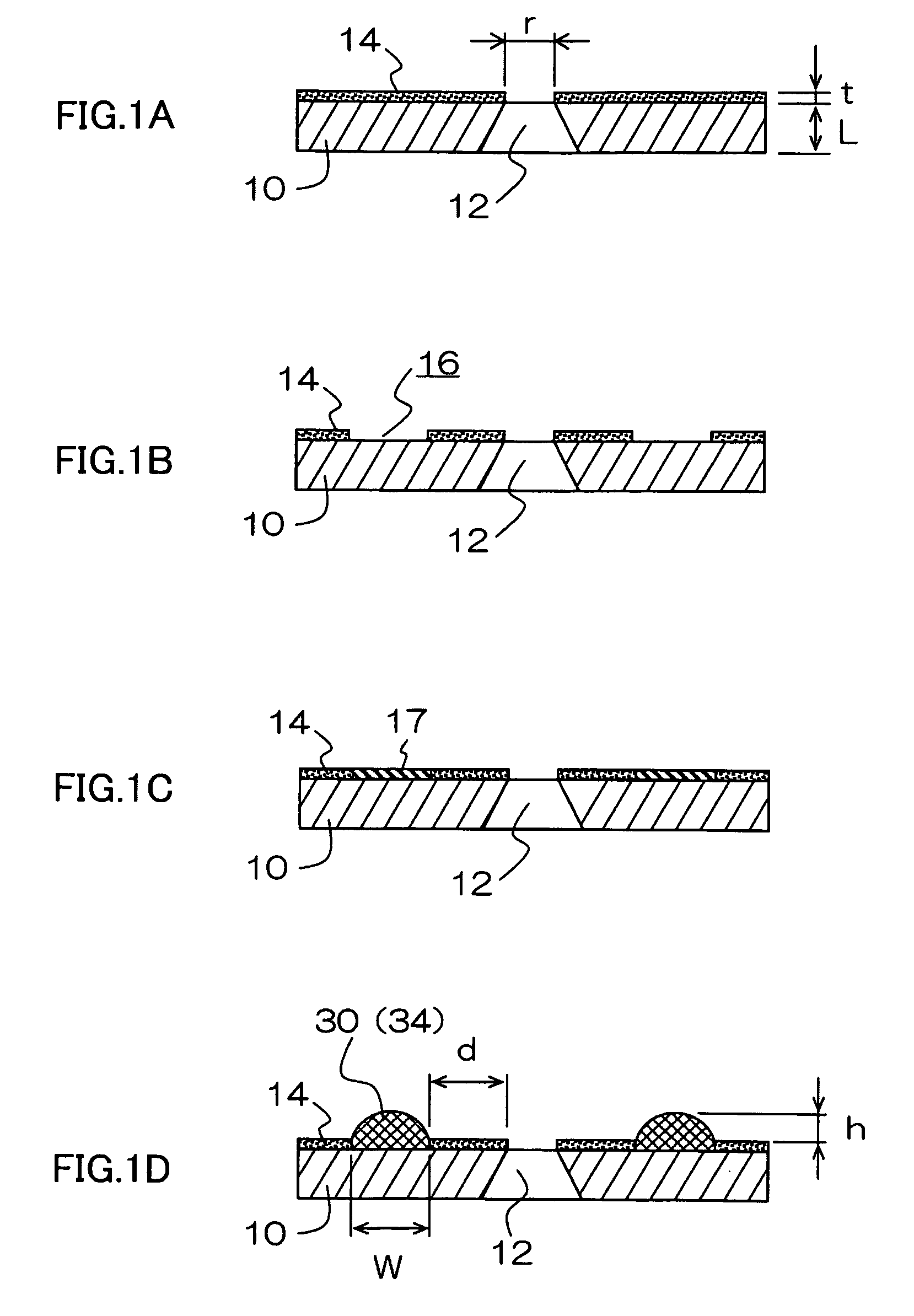
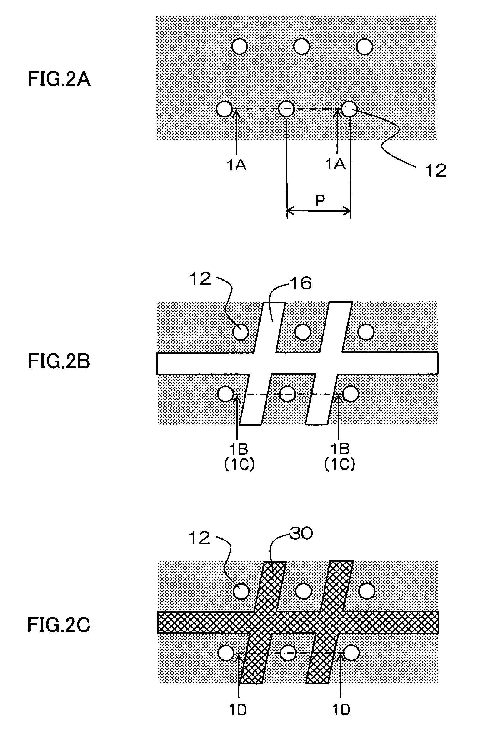
[0032]FIGS. 1A to 1D and FIGS. 2A to 2C are illustrative diagrams illustrating a method of manufacturing projecting sections in a nozzle plate relating to a first embodiment of the invention. FIGS. 1A to 1D are cross-sectional diagrams and FIGS. 2A to 2C are plan diagrams illustrating a nozzle plate viewed from the ejection direction. FIG. 1A illustrates a cross-sectional view along line 1A-1A in FIG. 2A, FIGS. 1B and 1C illustrate a cross-sectional view along line 1B-1B (1C-1C) in FIG. 2B, and FIG. 1D illustrates a cross-sectional view along line 1D-1D in FIG. 2C.

[0033]In FIGS. 1A to 1D, reference numeral 10 is a nozzle plate (which corresponds to a “substrate”) and reference numeral 12 is a nozzle (an aperture forming a liquid ejection port). The upper side in FIGS. 1A to 1D is the ejection surface side, and the liquid passing through a nozzle 12 is ejected from the lower to the upper side in FIGS. 1A to 1D.

Step 1: Step of Forming Nozzles and Lyophobic Film

[0034]Firstly, as illust...

second embodiment

[0056]As illustrated in FIGS. 2A to 2C above, the shape of the projecting sections 34 when the nozzle plate 10 is viewed from the direction of ejection may adopt a simple lattice shape whereby the perimeter of respective nozzles 12 is surrounded with a square shape, but from the viewpoint of the ink removal properties, and the wiping properties, it is also desirable to adopt the modes which are illustrated in FIGS. 5 to 7.

[0057]The examples in FIG. 5 and FIG. 6 are modes where the projecting sections composed of resin are formed in a dotted (broken line) configuration. According to these modes, when a blade is moved in one direction indicated by the white arrow in the drawings during a wiping action, the surplus ink wiped and collected by the blade is pushed and removed to one side by passing through the break portions (gaps) in the projecting sections 35, and therefore the ink removal properties during wiping are improved.

[0058]Furthermore, in the lattice-shaped mode illustrated in...

third embodiment

[0063]FIG. 7 illustrates a further mode which corresponds to a mode developed from that illustrated in FIG. 6. In the example in FIG. 7, the projecting sections 37 are formed by continuous curved lines which weave in a bending fashion between the nozzles 12 that are aligned in the wiping direction. The curve-shaped projecting sections 37 created by this resin are formed at a suitable oblique angle with respect to the wiping direction which reduces the damage caused by the blade. The example in FIG. 7 illustrates a mode in which an oblique line segment at approximately 45 degrees is bent back in a repeated fashion, and the oblique line segments are connected via bend portions being formed in a circular arc shape.


PUM


Abstract

A method of manufacturing at least one projecting section of a nozzle plate used in a liquid ejection head, includes: a partial lyophilic rendering step of rendering a lyophilic characteristic to a portion of a lyophobic film provided on an ejection surface side of a substrate in which a nozzle is formed, so as to form a lyophobic portion and a lyophilic portion on the ejection surface side of the substrate; a resin deposition step of depositing a curable resin on the lyophilic portion which has been rendered the lyophilic characteristic; and a curing step of curing the resin deposited on the lyophilic portion in such a manner that the cured resin forms the projecting section.

Description

CROSS-REFERENCE TO RELATED APPLICATIONS[0001]This application claims priority under 35 USC §119 from Japanese Patent Application No. 2008-053534, filed Mar. 4, 2008, the disclosure of which is incorporated herein by reference in its entirety.BACKGROUND OF THE INVENTION[0002]1. Field of the Invention[0003]The present invention relates to a method of manufacturing at least one projecting section of a nozzle plate in a liquid ejection head, and more particularly, to manufacturing technology which is suitable for forming a step section in the vicinity of a nozzle of an inkjet head.[0004]2. Description of the Related Art[0005]A composition for an inkjet head is known in which a step section (a so-called counterbore) is formed on the periphery of the nozzles in order to increase durability in respect of the mechanical breakdown of the liquid repelling film which is formed about the peripheral region of the nozzles, and the nozzles themselves, due to paper jamming, or the like (Japanese Pa...

Claims


Application Information

Patent Timeline
Patent Type & Authority Patents(United States)
IPC IPC(8): B05D5/00
CPCB41J2/0057B41J2/14233B41J2/1433B41J2/1606B41J2/162B41J2/1625B41J2/1626B41J2/1631B41J2/1634B41J2/1642B41J2/1643B41J2002/14459B41J2202/20
Inventor YOKOUCHI, TSUTOMU
Owner FUJIFILM CORP
Why Eureka
Try Eureka