Optical disc and method of manufacturing same

a technology of optical discs and optical discs, applied in the field of optical discs, can solve the problems of inability to separate the various materials, sharp fragments which must be handled with care, and failure to destroy the discs, etc., and achieve the effect of easy destruction, easy separation, and the same level of performan

Inactive Publication Date: 2011-09-06
TOPPAN PRINTING CO LTD +1
View PDF22 Cites 0 Cited by
  • Summary
  • Abstract
  • Description
  • Claims
  • Application Information

AI Technical Summary

Benefits of technology

[0025]An optical disc of the present invention uses, as a substrate, either a resin-impregnated paper produced by impregnating a paper with a resin, or a resin-coated paper produced by coating the surface of a paper with a resin, and the resin includes at least one resin selected from the group consisting of polycarbonates, bisphenol A epoxy resins, copolymers of methyl methacrylate and styrene, and copolymers of acrylonitrile and styrene. As a result, the optical disc exhibits the same level of performance as conventional discs, is able to be readily destroyed by cutting or peeling to enable information to be protected at the time of disposal, and provides a structure in which the recording layer can be readily separated from the substrate, the reflective layer and the recording layer can be separated and recovered with favorable efficiency and in a form that provides favorable transportation properties, and the separated substrate can be disposed of by incineration or ground burial, meaning the impact on the environment is minimal.
[0026]Furthermore, if the centerline average roughness Ra of at least one surface of the substrate is no higher than 0.5 μm, and the maximum height Rmax is no higher than 6.0 μm, then the surface smoothness improves, enabling a further improvement in the performance of the optical disc.
[0027]Furthermore, if a printed layer is provided on the opposite surface of the substrate to the surface on which the recording layer is provided, then water and moisture absorption by the substrate can be suppressed, and deformation of the optical disc, such as warping, can also be suppressed.
[0028]Similarly, if recording layers are provided on both surfaces of the substrate, then water and moisture absorption by the substrate can be suppressed, and deformation of the optical disc, such as warping, can also be suppressed.
[0029]Furthermore, if the optical disc also includes a protective layer that protects the recording layer, then not only is scratching of the recording layer prevented, but water and moisture absorption by the substrate can be further suppressed, enabling even better suppression of deformation of the optical disc, such as warping.
[0030]Furthermore, if the recording layer has a recording layer base material that functions as a support for the recording layer, and this recording layer base material is formed from a resin film, then water and moisture absorption by the substrate can be further suppressed, enabling even better suppression of deformation of the optical disc, such as warping.

Problems solved by technology

Although optical discs with this type of substrate exhibit excellent strength, attempts to destroy such discs by physical force at the time of disposal in order to protect the information contained thereon either result in failure to destroy the disc, or even if destruction is successful, generate sharp fragments which must be handled with care.
Furthermore, even if attempts are made to separate and recover the materials such as metals used in the reflective layer and the recording layer, to enable these materials to be reused, separating the various materials is impossible, making recycling extremely difficult.
Another problem that arises with conventional optical discs is that although printing methods, such as silk screen printing, are the most commonly used when lettering or images are printed on the surface of the disc, silk screen printing is unable to generate finely detailed images.
Furthermore, with silk screen printing, in order to enable different lettering or images to be printed on each disc, as in the case of serial numbers, the printing plate must be changed on each occasion, so that in the case of conventional optical discs, the printing of variable information onto each disc is not feasible from a practical viewpoint.

Method used


Image

  • Optical disc and method of manufacturing same
  • Optical disc and method of manufacturing same
  • Optical disc and method of manufacturing same

Examples


example 1 (

Preparation of Printed Sheet)

[0173]A stretched polylactic acid film of a thickness of 0.04 mm (Ecoloju®, manufactured by Mitsubishi Plastics, Inc.) was subjected to gravure printing using a biodegradable polyester-based printing ink (Biotech Color® HGP, manufactured by Dainichiseika Color & Chemicals Mfg. Co., Ltd.), thereby yielding a printed sheet on which was printed a display showing the type of optical disc, additional information relating to the optical disc, and a decorative image and the like.

Preparation of Substrate

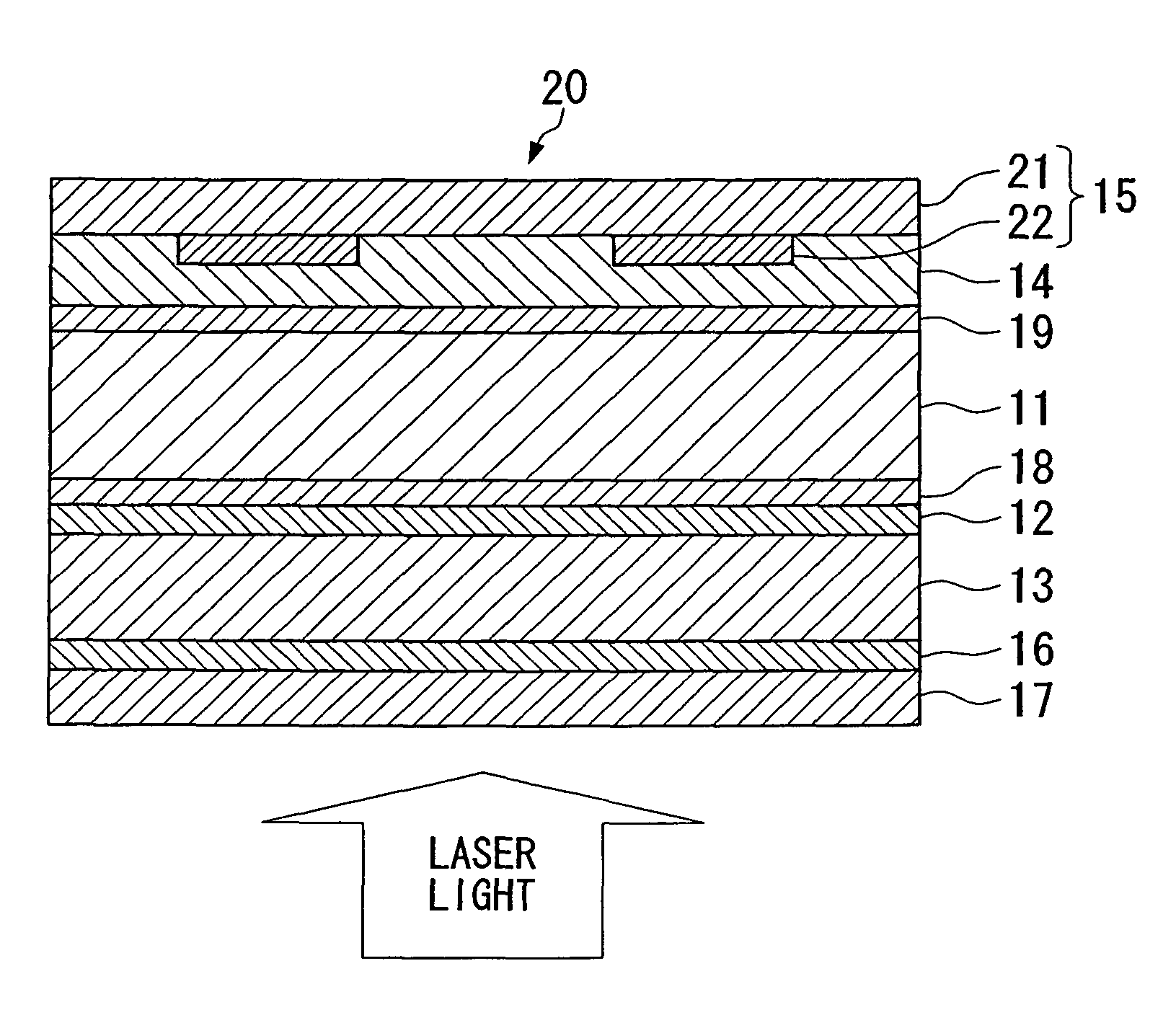
[0174]Adhesive layers formed from an adhesive were provided on both surfaces of a sheet of paper of a thickness of 0.6 mm, and polycarbonate films (sheets of Panlite®, manufactured by Teijin Ltd.) of a thickness of 0.18 mm were then bonded to both surfaces of the paper, thereby yielding a substrate with a thickness of 1.1 mm. Polyethylene was then coated onto both surfaces of the substrate by melt extrusion coating, thereby pre-forming release layers of a thickne...

example 2

[0185]With the exception of altering the preparation of the recording layer sheet in the manner described below, optical discs were prepared in the same manner as the Example 1.

Preparation of Recording Layer Sheet

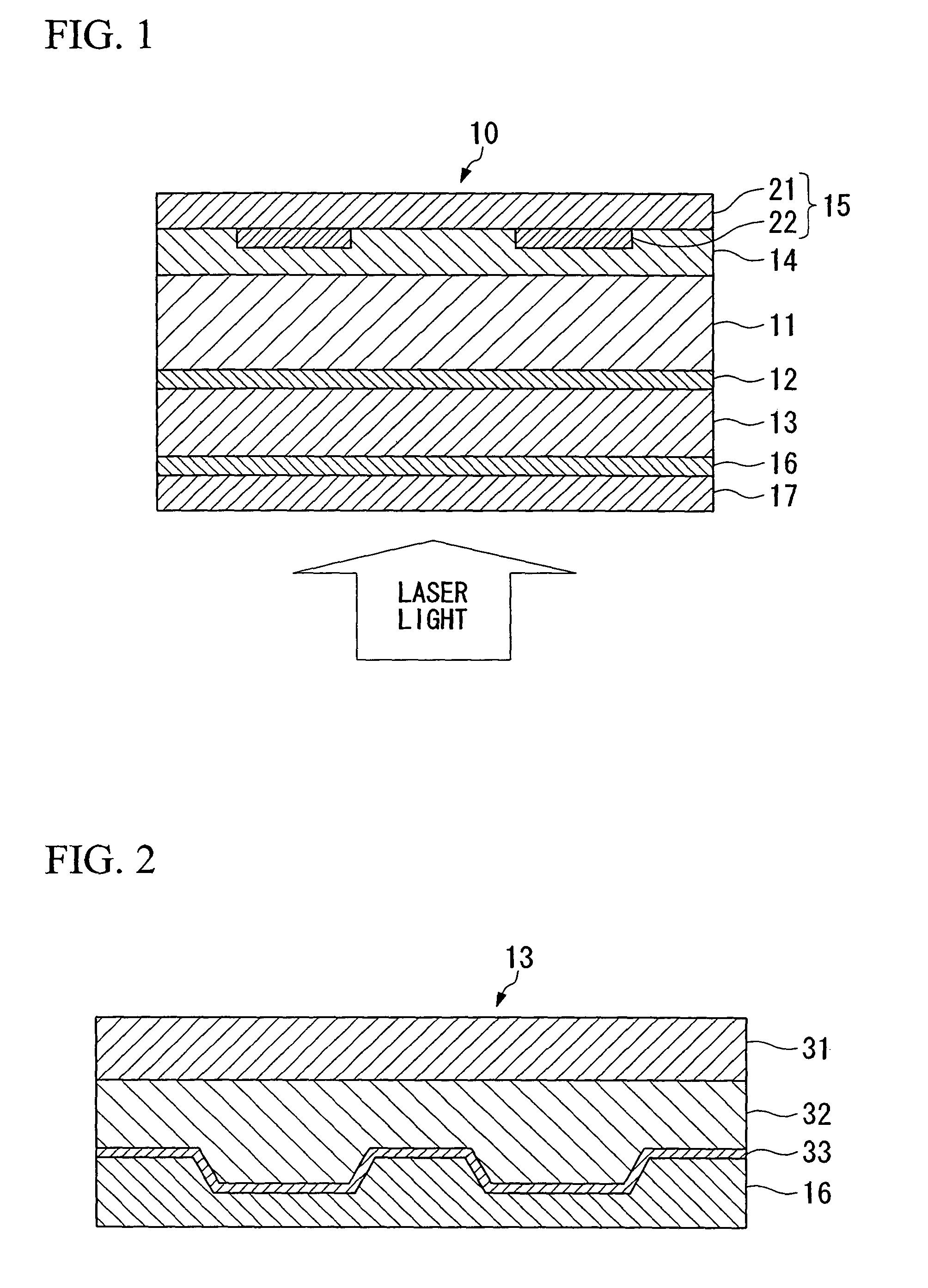
[0186]Surface projections / depressions that correspond with tracks were transferred to a copper-plated roll, and the roll was then subjected to chrome plating to form a transfer mold.

[0187]A stretched high density polyethylene film with a thickness of 0.05 mm was subjected to die coating with an ultraviolet curable resin in sufficient quantity to form a film thickness of 0.1 mm, and the transfer mold was then pressed against the film surface, thereby transferring the surface projections / depressions of the mold to the surface of the ultraviolet curable resin.

[0188]Subsequently, the ultraviolet curable resin was irradiated with ultraviolet light, thereby curing the ultraviolet curable resin and forming the tracks.

[0189]Aluminum was then deposited on the tracks by vacuum deposi...

example 3

[0193]With the exception of altering the preparation of the recording layer sheet in the manner described below, optical discs were prepared in the same manner as Example 1.

Preparation of Recording Layer Sheet

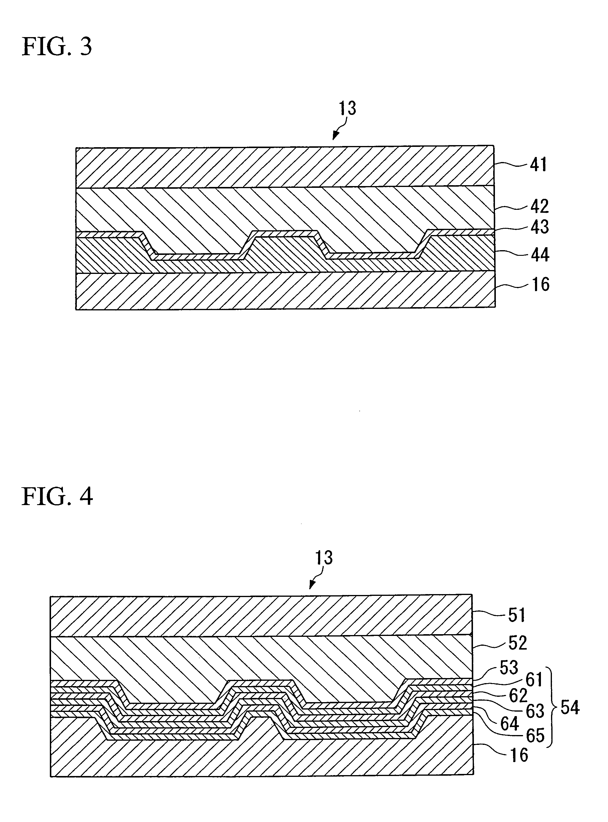
[0194]Surface projections / depressions that correspond with tracks were transferred to a copper-plated roll, and the roll was then subjected to chrome plating to form a transfer mold.

[0195]A stretched high density polyethylene film with a thickness of 0.05 mm was subjected to die coating with an ultraviolet curable resin in sufficient quantity to form a film thickness of 0.1 mm, and the transfer mold was then pressed against the film surface, thereby transferring the surface projections / depressions of the mold to the surface of the ultraviolet curable resin.

[0196]Subsequently, the ultraviolet curable resin was irradiated with ultraviolet light, thereby curing the ultraviolet curable resin and forming the tracks.

[0197]Aluminum was then deposited on the tracks by vacuum deposition...


PUM

PropertyMeasurementUnit
height Rmaxaaaaaaaaaa
surface smoothnessaaaaaaaaaa

Abstract

An optical disc (10) includes a substrate (11), which is formed from either a resin-impregnated paper produced by impregnating a paper with a resin, or a resin-coated paper produced by coating a surface of a paper with a resin, and a recording layer (13), wherein the resin contains at least one resin selected from the group consisting of polycarbonates, bisphenol A epoxy resins, copolymers of methyl methacrylate and styrene, and copolymers of acrylonitrile and styrene. Furthermore, a method of manufacturing an optical disc (20) includes: providing a recording layer sheet by forming tracks on a recording base material; and bonding the recording layer sheet to a resin-impregnated paper or a resin-coated paper, thereby providing a recording layer (13) formed from the recording layer sheet on the substrate (11).

Description

TECHNICAL FIELD[0001]The present invention relates to an optical disc, such as a Blu-ray disc (BD) or Digital Versatile Disc (DVD), and a method of manufacturing such a disc.[0002]Priority is claimed on Japanese Patent Application No. 2004-119523, filed Apr. 14, 2004, the content of which is incorporated herein by reference.BACKGROUND ART[0003]In order to enable stable reading and writing operations, substrate materials for conventional optical discs must contain minimal quantities of foreign substances or impurities, exhibit a high level of transparency, a small birefringence, a low level of moisture absorption to prevent deformation of the optical disc, and excellent heat resistance, and must also exhibit favorable fluidity and excellent releasability to ensure favorable molding characteristics, and consequently polycarbonates and epoxy resins and the like are widely used (for example, see Patent Document 1).[0004]Polycarbonates and epoxy resins can be heat molded, and may also be...

Claims


Application Information

Patent Timeline
Patent Type & Authority Patents(United States)
IPC IPC(8): B32B3/02G11B7/24G11B7/24027G11B7/24047G11B7/24094G11B7/24097G11B7/253G11B7/2533G11B7/26
CPCG11B7/24094G11B7/241G11B7/26
Inventor KINOSHITA, TOSHIROTANIGUCHI, MASAYUKIUMEYAMA, HIROSHIYAMASAKI, TAKESHIYUKUMOTO, TOMOMI
Owner TOPPAN PRINTING CO LTD
Why Eureka
Try Eureka