Starter voltage step-up device and combination of starter and of the voltage step-up device

a voltage step-up device and starter technology, applied in the direction of transformer/inductance magnetic cores, inductances, ac motor stoppers, etc., can solve the problem of inability to direct return after the production of a single layer of primary turns, and achieve the effect of improving the compactness of the devi

Active Publication Date: 2018-11-20
VALEO EQUIP ELECTRIC MOTEUR
View PDF10 Cites 0 Cited by
  • Summary
  • Abstract
  • Description
  • Claims
  • Application Information

AI Technical Summary

Benefits of technology

[0014]The objective of the invention is to improve the compactness of a device of this type whilst maintaining at least the same performance levels by proposing a starter battery voltage step-up device which is designed to prevent a drop of the battery voltage produced by a current surge from intervening in a power circuit of the said starter when it is switched on, comprising a casing made of magnetic material, a primary winding circuit which is designed to be inserted in series in the said power circuit, and a secondary, short-circuited winding circuit, wherein the said primary winding circuit and / or the said secondary winding circuit comprise(s) a winding formed from at least one conductor in the form of a field wound flattened part.
[0015]It is clear that persons skilled in the art understand “field wound” to mean the fact of winding with the larger side of the flattened part oriented according to the radius. The invention thus makes it possible to obtain a substantial reduction of the length, the weight and the volume of the device, as well as of the resistance of the winding W2, whilst complying with the same constraints of resistance. The invention also makes it possible to reduce the clearance according to the height between the winding and the head, taking into account the helix pitch which is reduced relative to the winding on a flattened part.

Problems solved by technology

In this respect, it will be noted that a direct return after the production of a single layer of primary turns would not have been possible with a conductor wound on a flattened part, because of the impossibility of bending.

Method used


Image

  • Starter voltage step-up device and combination of starter and of the voltage step-up device
  • Starter voltage step-up device and combination of starter and of the voltage step-up device
  • Starter voltage step-up device and combination of starter and of the voltage step-up device

Examples


Embodiment Construction

)

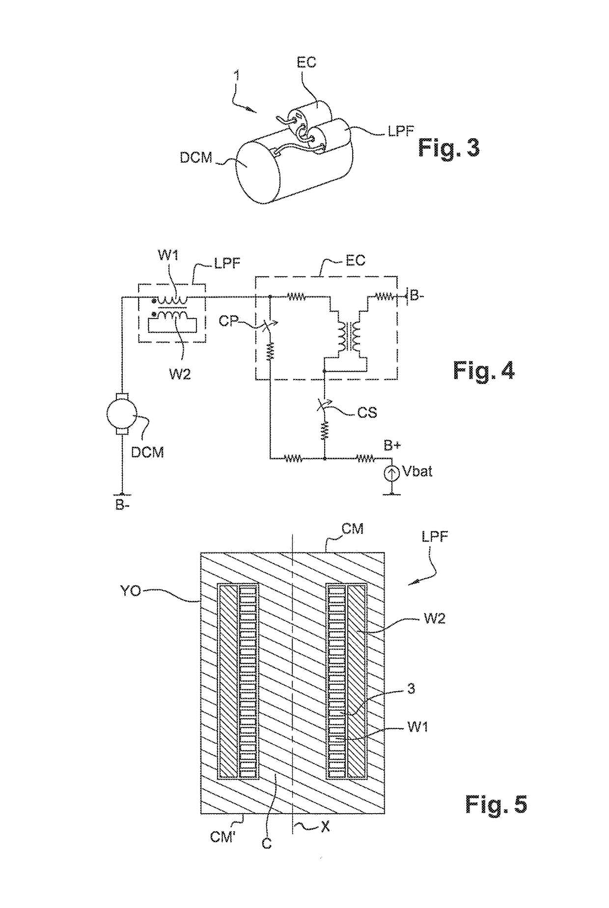
[0040]FIG. 3 shows a combination 1 of a starter, comprising a direct current electric motor DCM and an electromagnetic contactor EC, and a voltage step-up device consisting of a filtering device LPF of an inductive type. In this embodiment, the filtering device LPF is secured mechanically on an outer housing of the starter, in the vicinity of the contactor EC.

[0041]The electrical connections between the filtering device LPF, the contactor EC and the electric motor DCM are shown in FIG. 4. The filtering device LPF is fitted electrically in series between the power contact CP of the contactor EC and the motor DCM.

[0042]In an alternative embodiment (not represented), the filtering device LPF is not integrated in the starter EC, DCM, but is inserted in the power circuit between the positive terminal B+ of the battery and the power contact CP.

[0043]The contactor EC is in this case a conventional starter contactor with a simple power contact CP, and comprises a solenoid formed by a pull-...


PUM

PropertyMeasurementUnit
currentaaaaaaaaaa
voltageaaaaaaaaaa
voltageaaaaaaaaaa

Abstract

A starter battery voltage step-up device (LPF) intended to prevent a drop in the battery voltage (Vbat) produced by a current surge in a power circuit of the starter when the starter is powered on. The device comprises a casing of magnetic material (C, YO, CM, CM′), a primary winding circuit (W1) intended to be inserted in series in the power circuit, and a short-circuited secondary winding circuit (W2), in which the primary winding circuit (W1) and / or the secondary winding circuit (W2) comprises a winding formed by at least one flat conductor (3) wound on edge. The invention also relates to the corresponding combination (1) of a starter and a voltage step-up device.

Description

CROSS-REFERENCE TO RELATED APPLICATIONS AND CLAIM TO PRIORITY[0001]This application is a national stage application of International Application No. PCT / FR2014 / 051683 filed Jul. 1, 2014, which claims priority to French Patent Application No. 1356361 filed Jul. 1, 2013, the disclosures of which are incorporated herein by reference and to which priority is claimed.FIELD OF THE INVENTION[0002]In general, the invention relates to the field of starters for a thermal engine in motor vehicles. This field also incorporates starters which ensure an alternator function known as “alternator-starters”. More particularly, the invention concerns a device for stepping up the voltage at the terminals of the vehicle battery when the starter is switched on.BACKGROUND OF THE INVENTION[0003]When a starter is switched on in order to ensure the starting of the thermal engine of the vehicle, a substantial current requirement arises which is close to the short-circuit current level of the starter, i.e. a c...

Claims


Application Information

Patent Timeline
Patent Type & Authority Patents(United States)
IPC IPC(8): H01F27/24H01F37/00F02N11/08H02P1/18H01F27/28H02P1/04
CPCF02N11/087F02N11/08H01F27/24H01F27/2847H02P1/04H02P1/18H01F37/00F02N2250/02F02N2011/0892
Inventor ALLA, TARIKLABBE, NICOLASANDREUX, RAPHAELBALEYDIER, BENO TJACQUIN, PASCALSANCHEZ, JOSERIOU, BERTRAND
Owner VALEO EQUIP ELECTRIC MOTEUR
Why Eureka
Try Eureka