Apparatus and method for providing energy—bandwidth tradeoff and waveform design in interference and noise

a technology of interference noise and amplifier, applied in the field of amplifier and method for providing energy, can solve the problems of releasing otherwise unavailable bandwidth at the expense of additional signal energy, and achieve the effect of minimizing total interference and noise output, enhancing desired signal output, and sacrificing performance level

Inactive Publication Date: 2010-05-04
C & P TECH
View PDF7 Cites 1 Cited by
  • Summary
  • Abstract
  • Description
  • Claims
  • Application Information

AI Technical Summary

Benefits of technology

[0027]One or more embodiments of the present invention provide a method and an apparatus for transmitter-receiver design that enhances the desired signal output from the receiver while minimizing the total interference and noise output at the desired decision making instant. Further the method and apparatus of an embodiment of the present invention can be used for transmit signal energy-bandwidth tradeoff. As a result, transmit signal energy can be used to tradeoff for “premium” signal bandwidth without sacrificing performance level in terms of the output Signal to Interference plus Noise power Ratio (SINR). The two designs—before and after the tradeoff—will result in two different transmitter-receiver pairs that have the same performance level. Thus a design that uses a certain energy and bandwidth can be traded off with a new design that uses more energy and lesser bandwidth compared to the old design. In many applications such as in telecommunications, since the available bandwidth is at premium, such a tradeoff will result in releasing otherwise unavailable bandwidth at the expense of additional signal energy. The bandwidth so released can be used for other applications or to add additional telecommunications capacity.

Problems solved by technology

In many applications such as in telecommunications, since the available bandwidth is at premium, such a tradeoff will result in releasing otherwise unavailable bandwidth at the expense of additional signal energy.

Method used


Image

  • Apparatus and method for providing energy—bandwidth tradeoff and waveform design in interference and noise
  • Apparatus and method for providing energy—bandwidth tradeoff and waveform design in interference and noise
  • Apparatus and method for providing energy—bandwidth tradeoff and waveform design in interference and noise

Examples


Embodiment Construction

—Desired Band Approach

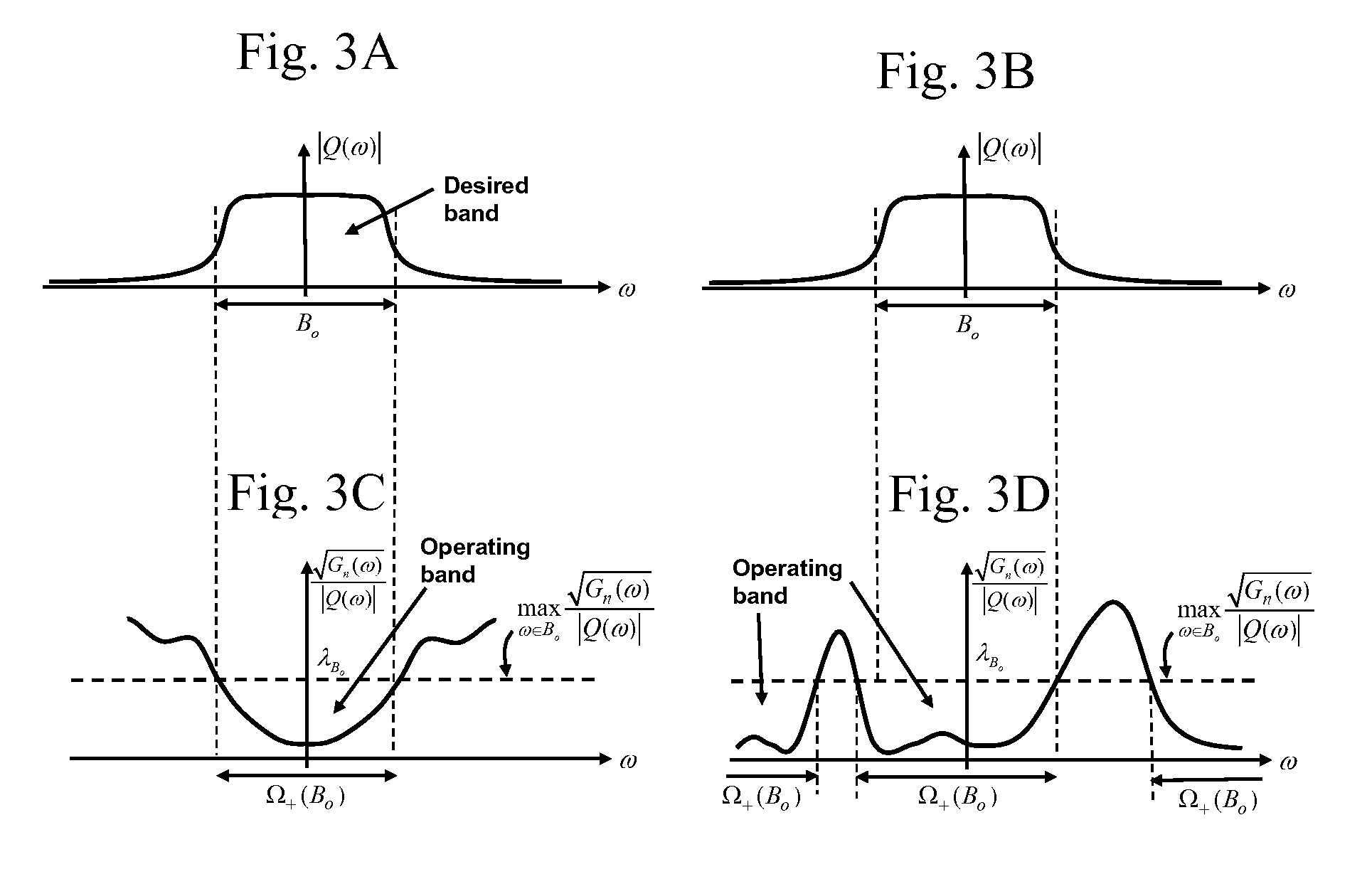
[0094]One approach in this situation is to make use of the “desired frequency band” of interest B0 this is usually suggested by the target response Q(ω) (and the transmitter output filter) to determine the operating band Ω+. The desired band B0 can represent a fraction of the total available bandwidth, or the whole bandwidth itself. The procedure for determining Ω+ is illustrated in FIGS. 3A-3C and FIGS. 3B-3D for two different situations. In FIGS. 3A-3D, the frequency band B0 represents the desired band, and because of the nature of the noise and clutter spectra, it may be necessary to operate on a larger region Ω+ in the frequency domain. Thus the desired band B0 is contained always within the operating band Ω+. To determine Ω+, using equation (23) we project the band B0 onto the spectrum √{square root over (Gn(ω))} / |Q(ω)| and draw a horizontal line corresponding to

[0095]λBo=maxω∈Bo⁢Gn⁡(ω)Q⁡(ω)(32)

as shown there. Define Ω+(B0 ) to represent the frequency regi...


PUM

PropertyMeasurementUnit
frequencyaaaaaaaaaa
energyaaaaaaaaaa
transmit signal energyaaaaaaaaaa

Abstract

A new method for transmitter-receiver design that enhances the desired signal output from the receiver while minimizing the total interference and noise output from the receiver at the desired decision making instant is presented. Further the new design scheme proposed here can be used for transmit signal energy and bandwidth tradeoff. As a result, transmit signal energy can be used to tradeoff for the “premium” signal bandwidth without sacrificing the system performance level in terms of the output Signal to Interference plus Noise power Ratio (SINR). The two designs—the one before and the one after the tradeoff—will result in two different transmitter-receiver pairs that have the same performance level. In many applications such as in telecommunications, since the available bandwidth is at premium, such a tradeoff will result in releasing otherwise unavailable bandwidth at the expense of additional signal energy. The bandwidth so released can be used for other applications or to add additional telecommunication capacity to the system.

Description

STATEMENT REGARDING FEDERALLY SPONSORED RESEARCH OR DEVELOPMENT[0001]The present invention is based upon work supported and / or sponsored by the Air Force Research Laboratory (AFRL), Rome, N.Y. under contract No. FA8750-06-C-0202FIELD OF INVENTION[0002]The invention relates to techniques related to a tradeoff between transmit signal Energy and its Bandwidth using new transmitter-receiver waveform design methods that are applicable for radar, sonar and wireless communications.BACKGROUND OF INVENTION[0003]In the general problem, a desired target is buried in both interference and noise. A transmit signal excites both the desired target and the interference simultaneously. The interference and / or interferences can be foliage returns in the form of clutter for radar, scattered returns of the transmit signal from a sea-bottom and different ocean-layers in the case of sonar, or multipath returns in a communication scene. In all of these cases, like the target return, the interference retur...

Claims


Application Information

Patent Timeline
Patent Type & Authority Patents(United States)
IPC IPC(8): H04B1/00H04L27/00G01N30/86H03K5/01
CPCH04L1/0017G01S7/282
Inventor PILLAI, UNNIKRISHNA SREEDHARAN
Owner C & P TECH
Why Eureka
Try Eureka