Engine brake for part load CO reduction

a turbine engine and co reduction technology, applied in steam engine plants, machines/engines, mechanical equipment, etc., can solve the problems of high carbon monoxide (co) production during combustion, and achieve the effects of reducing operating load, reducing power delivered by the engine assembly, and increasing the flow rate through the bleed lin

Active Publication Date: 2011-09-13
SIEMENS ENERGY INC
View PDF33 Cites 58 Cited by
  • Summary
  • Abstract
  • Description
  • Claims
  • Application Information

AI Technical Summary

Benefits of technology

[0007]Aspects of the invention relate to a system and method for operating a turbine engine assembly. The turbine engine assembly has a turbine engine having a compressor section, a combustor section and a turbine section. The combustor section has a lower T_PZ limit and the turbine engine has a design load. The assembly further includes at least one air bleed line from the compressor and at least one valve for controlling air flow through the bleed line. Control structure is provided for opening the valve to allow bleed air to flow through the bleed line when an operating load is less than the design load. The flow rate through the bleed line is increased as the operating load is decreased, reducing the power delivered by the engine assembly while maintaining the T_PZ above a lower T_PZ limit.
[0008]Another aspect of the invention is directed to a method of operating a turbine engine assembly, the turbine engine assembly comprising a compressor section, a combustor section, and a turbine section. The combustor section has a lower T_PZ limit. The method includes sensing the load on the turbine engine assembly for a reduced operating load; and bleeding air from the compressor section responsive to the reduced operating load. The flow rate of the bleed air is increased as the operating load is decreased, reducing the power delivered by the turbine assembly and maintaining the T_PZ above the lower T_PZ limit.

Problems solved by technology

Part load operation may result in the production of high levels of carbon monoxide (CO) during combustion.

Method used


Image

  • Engine brake for part load CO reduction
  • Engine brake for part load CO reduction
  • Engine brake for part load CO reduction

Examples


Embodiment Construction

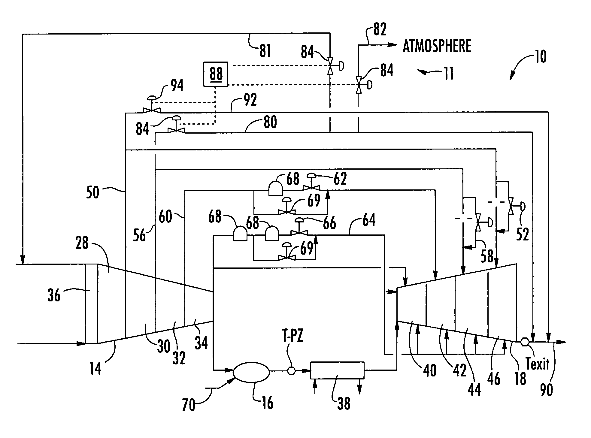
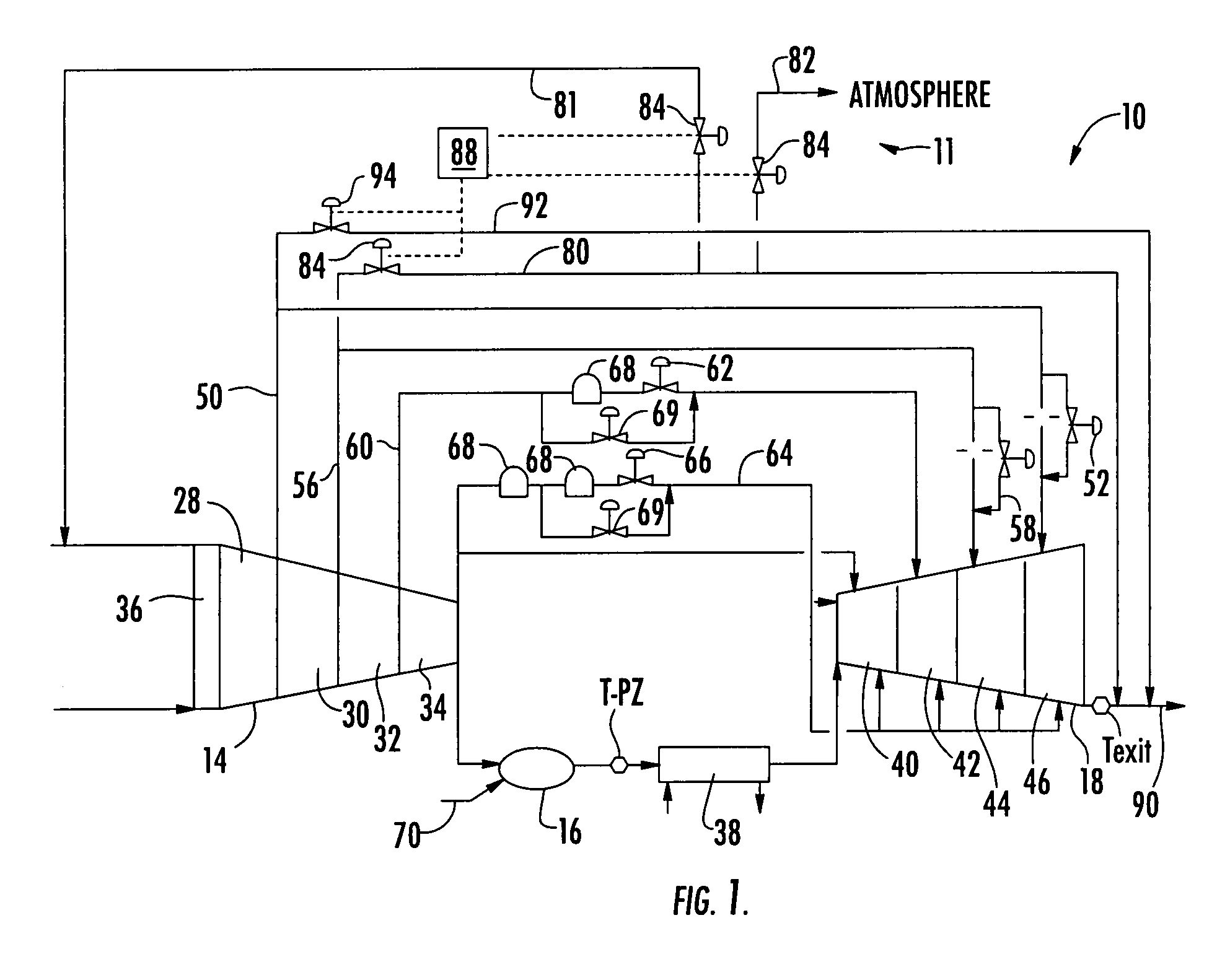
[0014]Embodiments of the invention are directed to a turbine engine assembly 10 having a compressor section 14, a combustor section 16, and a turbine section 18. As is known in the art, the compressor 14 can have one or more stages such as front stages 28, forward stages 30, middle stages 32, and rear stage 34. Also, the compressor 14 can have inlet guide vanes (IGV) 36 which can be opened and closed or otherwise adjusted to control the mass flow of air into the compressor 14. It should be understood that turbine assembly 10 can have other vane assemblies and other assemblies that provide for flow control, including variable stator vanes. The combustor section 16 is shown as a single unit, but it should be understood that in most turbine engines the combustor section 16 can comprise a plurality of combustion chambers. A transition section or structure 38 can be provided for directing of the combustion flow. The turbine section can comprise one or more stages such as first stage 40, ...


PUM


Abstract

Aspects of the invention relate to a system and method for operating a turbine engine assembly. The turbine engine assembly has a turbine engine having a compressor section, a combustor section and a turbine section. The combustor section has a lower T_PZ limit and the turbine engine has a design load. The assembly further includes at least one air bleed line from the compressor and at least one valve for controlling air flow through the bleed line. Control structure is provided for opening the valve to allow bleed air to flow through the bleed line when an operating load is less than the design load. The flow rate through the bleed line is increased as the operating load is decreased, reducing the power delivered by the turbine assembly while maintaining the T_PZ above a lower T_PZ limit. A method for operating a turbine engine assembly is also disclosed.

Description

FIELD OF THE INVENTION[0001]Aspects of the invention relate in general to turbine engines and, more particularly, to part load CO reduction in a turbine engine.BACKGROUND OF THE INVENTION[0002]Turbine engines, such as single shaft industrial gas turbines, are designed to operate at a constant design turbine inlet temperature under any ambient air temperature (i.e., the compressor inlet temperature). This design turbine inlet temperature allows the engine to produce maximum possible power, known as base load. Any reduction from the maximum possible base load power is referred to as part load operation. In other words, part load entails all engine operation from 0% to 99.9% of base load power.[0003]Part load operation may result in the production of high levels of carbon monoxide (CO) during combustion. One known method for reducing part load CO emissions is to bring the combustor exit temperature or the turbine inlet temperature near that of the base load design temperature. It shoul...

Claims


Application Information

Patent Timeline
Patent Type & Authority Patents(United States)
IPC IPC(8): F02C6/04
CPCF01K13/02F02C9/18F02C9/20F05D2270/08
Inventor MYERS, GERALD A.LITTLE, DAVID A.
Owner SIEMENS ENERGY INC
Why Eureka
Try Eureka