
Method of forming metal

a metal forming and high-speed technology, applied in the field of magnet coils, can solve the problems of puckering or other defects, material poor conductors cannot be effectively formed, and aluminum alloy press forming and specialty steels

Inactive Publication Date: 2011-09-13
AMERICAN TRIM
View PDF11 Cites 28 Cited by
  • Summary
  • Abstract
  • Description
  • Claims
  • Application Information

AI Technical Summary

Benefits of technology

"The invention is a coil assembly for high velocity metal forming, which includes an inner coil and an outer coil. The inner coil has a flattened helix shape and is coated with resin to prevent electrical contact with the outer coil. The outer coil has a cavity filled with resin. The actuator process involves forming a hole in a conductive metal block, cutting out a central portion to form the inner coil, and machining angled notches and straight slots in the inner coil. The inner coil is then inserted into the outer coil and the space surrounding it is filled with resin. The invention also includes a metal forming system with a coil assembly and a hydraulic press. The technical effects of the invention include improved metal forming efficiency and accuracy."

Problems solved by technology

Materials which are poor conductors can only be effectively formed with electromagnetic energy if an auxiliary driver plate of high conductivity is used to push the workpiece.
Puckers or other defects can form when the launch velocity of the metal workpiece is not uniform.
Press forming of aluminum alloys and specialty steels has presented challenges, relative to low carbon steel, principally due to the very low strain rate hardening, low r (strain ratio) value and high galling tendency of such materials.
Wrinkling, splits and other defects can occur in aluminum panels within the first 25% of the tool stroke using conventional forming techniques.
Stainless steel and other specialty steels are also subject to cracking (breakage), and they can contribute to excessive tool wear when conventional forming techniques are employed.
To date, the use of non-symmetric forming has not been commercially feasible for most applications because the actuators have displayed minimal life.
Actuators are relatively expensive to produce, and limited actuator life makes non-symmetric forming too costly.

Method used


Image

  • Method of forming metal
  • Method of forming metal
  • Method of forming metal

Examples


first embodiment

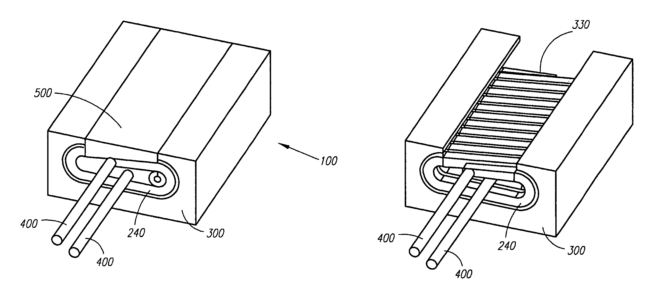
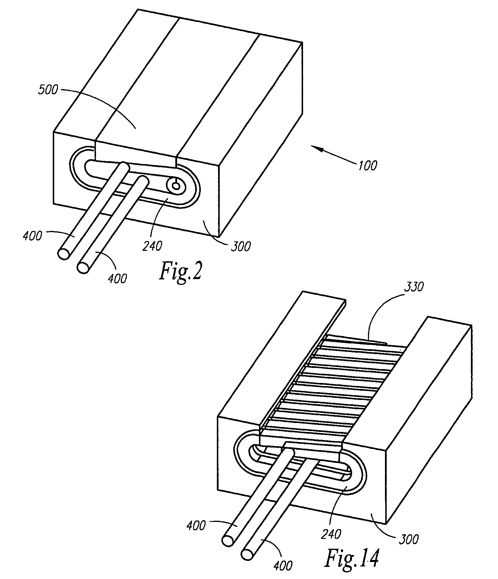
[0054]the invention is an actuator, which is a coil assembly, for use in high velocity metal forming comprising an inner coil and an outer coil. The inner coil generally has the shape of a flattened helix, and the outer coil includes a cavity therein. The inner and outer coils are generally coaxial. Leads connect the inner coil to an outside electrical power source. A resin coats the inner coil, and the inner coil is situated inside the cavity of the outer coil such that the inner and outer coils are not in electrical contact with one another, and such that the cavity of the outer coil is substantially filled with the resin. The inventors hereof believe that the use of a flattened helix is important to generate a non-uniform magnetic field (leading to non-symmetric forming operations) as opposed to a cylindrical helix, which generates a uniform magnetic field leading to symmetric forming operations.

[0055]A preferred embodiment is a uniform pressure activator (“Uactivator”) which car...

second embodiment

[0056]the invention is a process for making a high velocity metal forming (HVMF) actuator assembly wherein the assembly comprises an inner and an outer coil, the process comprising:[0057]a. forming a hole through a block of conductive metal or alloy having X, Y, and Z dimensions, said hole being formed in the Z dimension;[0058]b. beginning at the hole, cutting out a continuous central portion of the block corresponding to a desired inner dimension of an inner coil, said cutting being substantially parallel to the Z-axis;[0059]c. cutting out a further portion of the block parallel to the Z-axis to form an inner coil, the remainder constituting an outer coil having a cavity;[0060]d. machining angled notches in a +Z portion of the inner coil at regular intervals along the X-axis, said angled notches being cut at an angle of 0 to 90° from the X-axis;[0061]e. machining straight slots in a −Z portion of the inner coil, said straight slots being substantially parallel to the Y-axis, to aff...


PUM

PropertyMeasurementUnit
angleaaaaaaaaaa
angleaaaaaaaaaa
velocitiesaaaaaaaaaa

Abstract

Electromagnetic forming can lead to better formability along with additional benefits. The spatial distribution of forming pressure in electromagnetic forming can be controlled by the configuration of the actuator. A type of actuator is discussed which gives a uniform pressure distribution in forming. It also provides a mechanically robust design and has a high efficiency for flat sheet forming.

Description

CROSS-REFERENCE TO RELATED APPLICATIONS[0001]This application is related to U.S. provisional utility application Nos. 60 / 978,160, filed Oct. 8, 2007, entitled METHOD OF FORMING METAL; 61 / 049,082 filed on Apr. 30, 2008, entitled EMF ACTUATOR AND COUPLING SYSTEM, and 61 / 059,841, filed Jun. 9, 2008, entitled METHOD OF FORMING METAL, the entireties of all of which are incorporated herein by reference.BACKGROUND OF THE INVENTION[0002]1. Field of Invention[0003]The invention concerns high velocity metal forming (HVMF). More particularly, the invention relates to a magnetic coil assembly (actuator) for use in electromagnetic forming as a reliable alternative to traditional metal-stamping or metal-forming operations. A method of using the actuator is also contemplated.[0004]2. Description of Related Art[0005]Electromagnetic forming is a method of forming sheet metal or thin walled tubes that is based on the method of placing a work-coil in close proximity to the metal to be formed and runni...

Claims


Application Information

Patent Timeline
Patent Type & Authority Patents(United States)
IPC IPC(8): B21D26/14B21D26/06
CPCB21D26/14H01F7/20H01F41/0691Y10S72/707H01F41/077
Inventor JONES, ALLEN M.WHETSTONE, DALE E.WILKERSON, LARRY A.HATKEVICH, STEPHEN C.
Owner AMERICAN TRIM
Learn More