
Fluid delivery system and sensing unit therefor

a technology of inline sensing unit and delivery system, which is applied in the direction of volume metering, process and machine control, instruments, etc., can solve the problems of limited medical use of hand-actuated syringes, insufficient accuracy of hand-actuated syringes, and many types of human errors

Active Publication Date: 2011-09-13
INTEGRATED SENSING SYST INC
View PDF2 Cites 14 Cited by
  • Summary
  • Abstract
  • Description
  • Claims
  • Application Information

AI Technical Summary

Benefits of technology

[0011]A fluid delivery system equipped with the inline sensing unit described above is capable of delivering a precise amount of fluid, in terms of mass flow rate and volumetric flow rate, and can be further used to sense dosage dispensed through the unit. The functionality of the sensing unit can be enhanced to include visual and / or audible signals in response to the density, flow rate, and / or dosage of the fluid. The fluid delivery system can also be equipped to store such data and other information in memory, and / or relay such data and information to a computer Based on the data and information, the flow of the fluid can be stopped if one or more of these parameters are outside preset limits. In this manner, the sensing unit is capable of monitoring blockage. Based on fluid density measurements, the sensing unit is also able to detect gas bubbles or another phase within the fluid, and can determine whether, based on density, the correct fluid is being delivered. This capability can also be employed to prevent medication delivery errors and avoid venous air embolisms.

Problems solved by technology

In these situations, hand-actuated syringes are often not sufficiently accurate.
Furthermore, hand-actuated syringes are prone to many types of human errors such as errors in dosage amount, dose rate, and medicine type.
Though Coriolis mass flow sensors can provide flow rate measuring accuracies of under + / −1%, their high cost and general requirements for relatively high flow rates have restricted their use in the medical field.

Method used


Image

  • Fluid delivery system and sensing unit therefor
  • Fluid delivery system and sensing unit therefor
  • Fluid delivery system and sensing unit therefor

Examples


Embodiment Construction

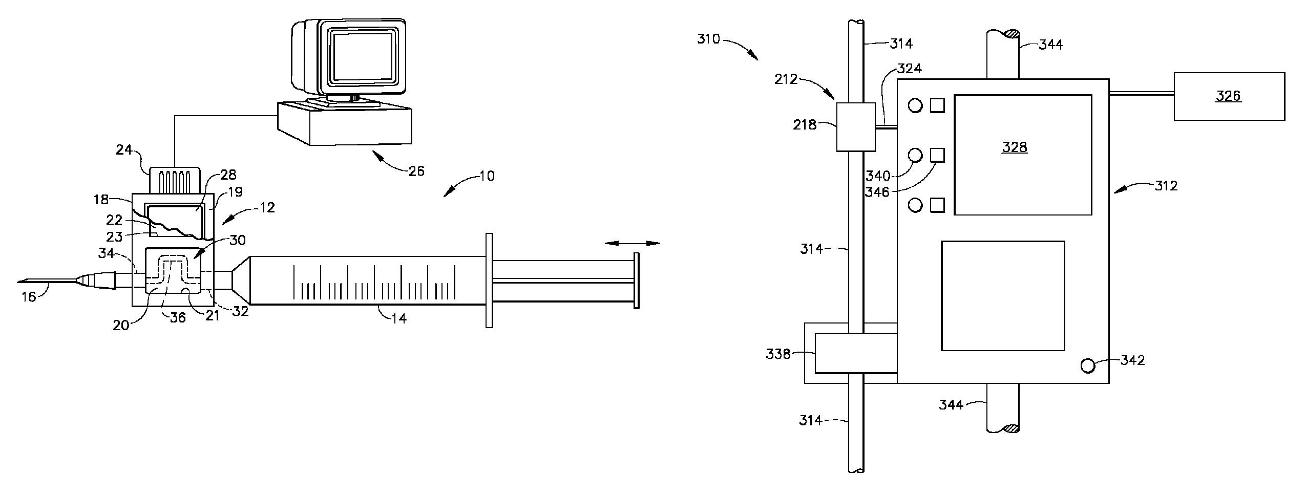
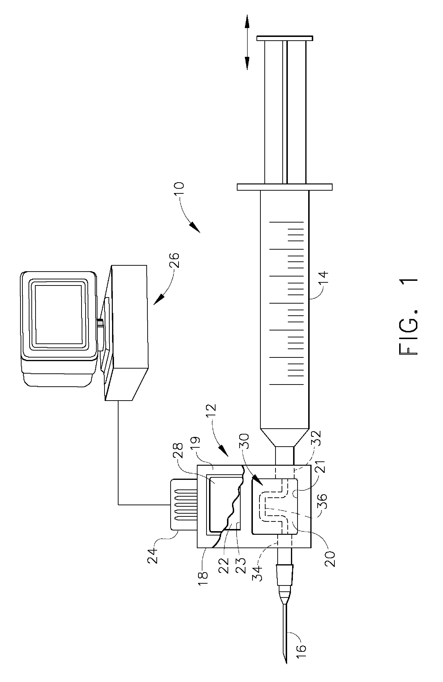
[0018]With reference to FIG. 1, a fluid delivery system 10 is shown that utilizes an inline sensing unit 12 through which a fluid flows for delivery from a manually-operated syringe 14, through a hypodermic needle 16, and to a patient. The sensing unit 12 is termed “inline” because the unit 12 is physically mounted between the fluid source and the device that delivers the fluid to its intended destination. As will become evident from the following, a variety of fluid sources could be used in place of the syringe 14, including Y-ties, septums, machine-controlled pumps, IV primer / drip chambers, etc. Furthermore, a variety of accessories could be used in place of the needle 16, including IV tubes, pipettes, cannula, catheters, etc. As such, the fluid delivery system 10 can be used to administer medications by a variety of methods, e.g., intravenous, intra-arterial, subcutaneous, intramuscular (IM), intraperitoneal (IP), intrathecal, transdermal, etc.

[0019]According to a preferred aspec...


PUM


Abstract

A fluid delivery system capable of delivering a precise amount of fluid, such as a fluid required for medical treatment. The delivery system makes use of an inline sensing unit that includes a housing comprising an inlet for receiving a fluid from a fluid source, an outlet for discharging the fluid from the housing, and at least one cavity between the inlet and the outlet. A sensing element and electronic circuitry are disposed within the at least one cavity. The electronic circuitry is adapted to produce an electrical output based on at least one response of the sensing element. The sensing unit is further equipped with a communication element for providing communication between the electronic circuitry and an electronic device remote from the housing.

Description

CROSS REFERENCE TO RELATED APPLICATIONS[0001]This application a continuation-in-part patent application of co-pending U.S. patent application Ser. No. 10 / 248,839 filed Feb. 24, 2003 to Sparks, now U.S. Pat. No. 6,932,114 and claims the benefit of U.S. Provisional Application No. 60 / 530,961, filed Dec. 10, 2003, and U.S. Provisional Application No. 60 / 469,134, filed May 12, 2003.BACKGROUND OF INVENTION[0002]1. Field of the Invention[0003]The present invention generally relates to fluid handling devices and methods for their use. More particularly, this invention relates to a fluid delivery system and an inline sensing unit capable of delivering controlled amounts of fluids.[0004]2. Description of the Related Art[0005]Infusion therapy generally involves the administration of a medication to a subject using intravenous (IV), subcutaneous and epidural routes. A wide variety of fluid infusion pumps have been developed over the years that are capable of delivering medication at a controll...

Claims


Application Information

Patent Timeline
IPC IPC(8): A61M5/00A61M5/142A61M5/168A61M5/36G01F1/84G01F13/00
CPCA61M5/16827A61M5/365G01F1/8445G01F1/8472G01F13/006G06F19/3468A61M5/142A61M5/16831A61M2205/0244A61M2205/3334A61M2230/201G16H20/17
Inventor SPARKS, DOUGLAS RAYNAJAFI, NADER
Owner INTEGRATED SENSING SYST INC
Learn More