Spinal implant with overlay

Active Publication Date: 2011-09-13
K2M
View PDF36 Cites 33 Cited by
  • Summary
  • Abstract
  • Description
  • Claims
  • Application Information

AI Technical Summary

Benefits of technology

[0042]Another embodiment of the current invention can be described as a method of improving stability of an implant capable of implantation into a surgically created cavity between a superior vertebra and an inferior vertebra, wherein the implant comprises a face including a first vertical post, a second vertical post and a plurality of horizontal cross members interconnected with the first vertical post and the second vertical post; said method comprising the steps of: a) providing an overlay composed of titanium, stainless steel, polymers or combinations thereof, wherein said overlay further

Problems solved by technology

To introduce an implant that is taller at its insertion end than the space available at the poste

Method used


Image

  • Spinal implant with overlay
  • Spinal implant with overlay
  • Spinal implant with overlay

Examples


Example

[0074]Although the disclosure hereof is detailed to enable those skilled in the art to practice the invention, the embodiments published herein merely exemplify the present invention.

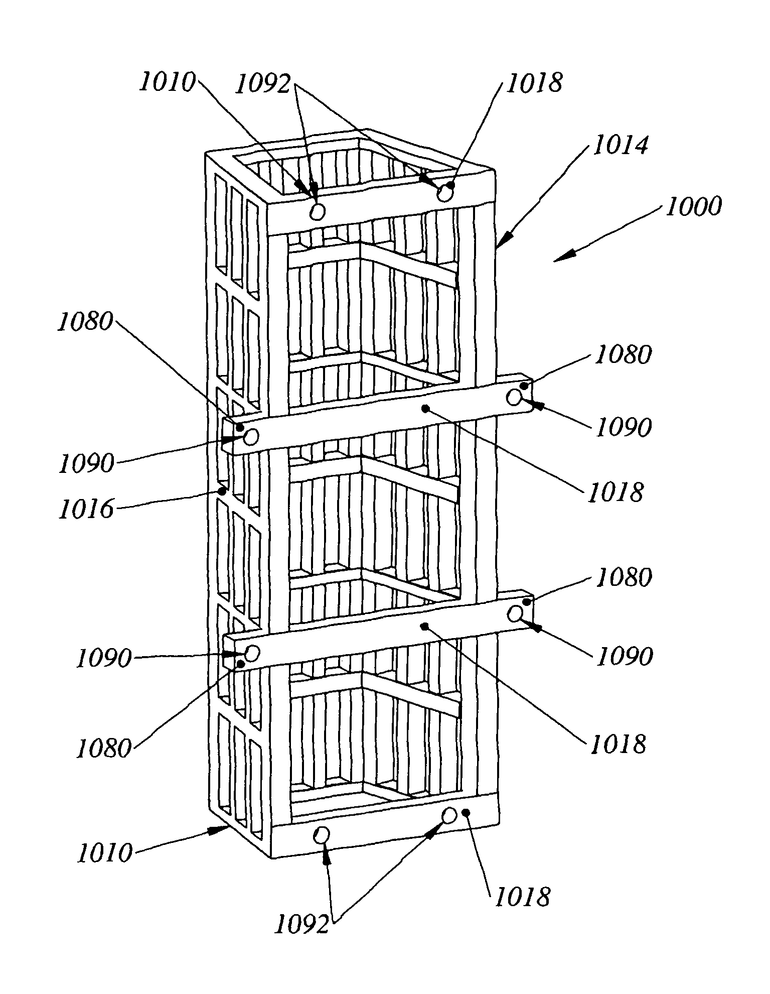
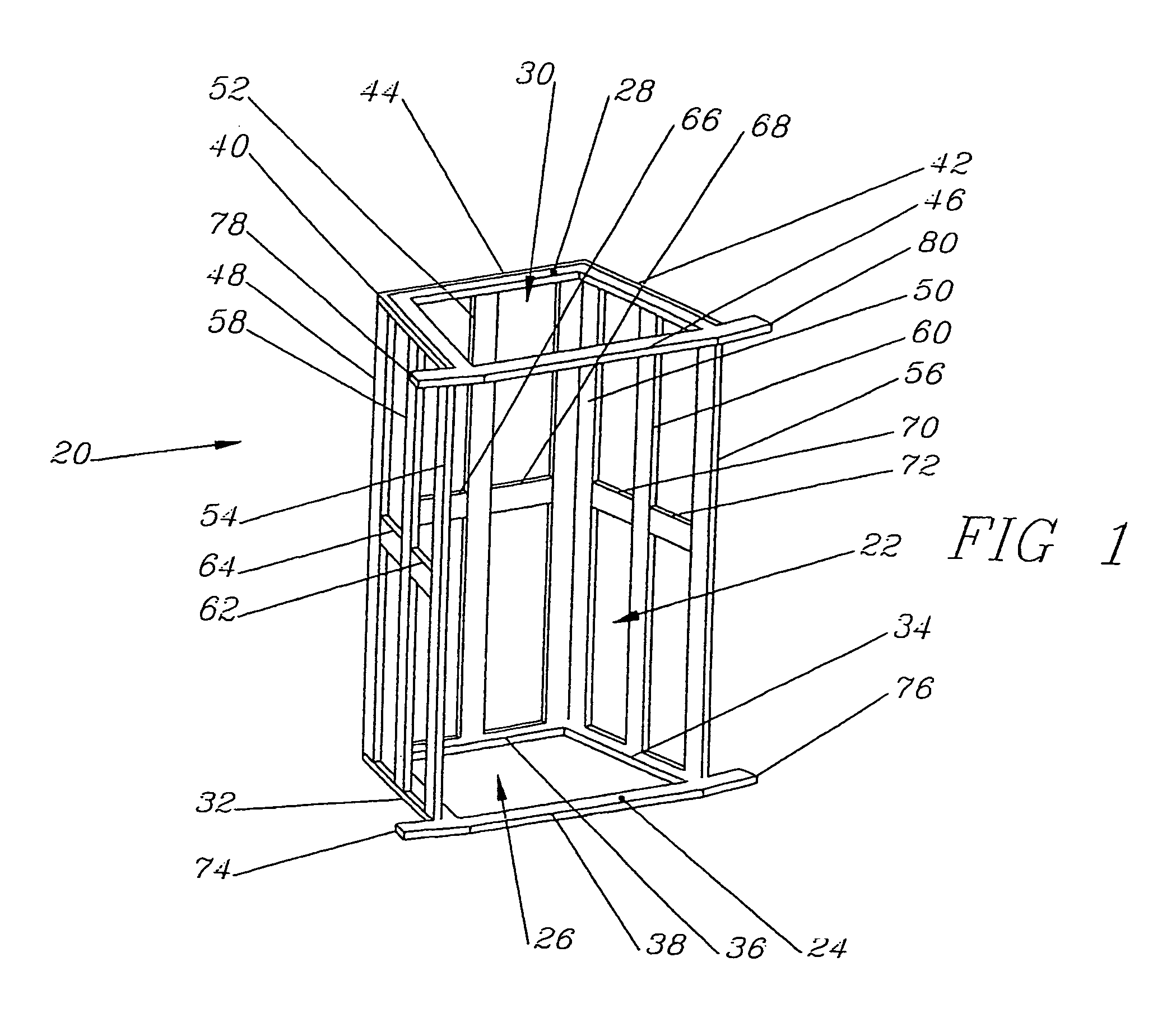
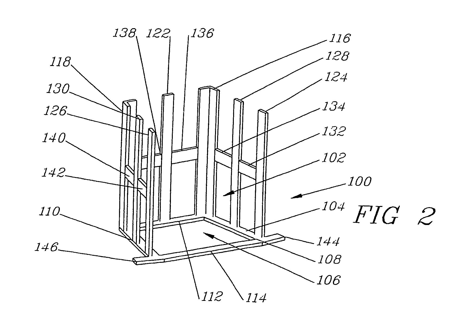
[0075]In the most general sense, the present invention is a brace or implant that can be inserted into a cavity of the spinal column. Surgical removal of at least a part of one or more vertebra creates the cavity that will receive the implant. It has been discovered that many embodiments of the current implant can be useful for cervical spine surgeries and can assist in stabilization of the postoperative spine. And many of the preferred embodiments of the present invention are particularly suited for corpectomy or partial corpectomy procedures.

[0076]After insertion of the brace into the cavity, the brace assists in stabilizing the spinal column against rotational movement and also resists the compression forces associated with gravitational forces on the spinal column. Select embodiments of the present ...


PUM


Abstract

A spinal implant and an overlay for interlocking with the face of the spinal implant. Grooves and/or channels of the overlay interlock with the face of the implant. The overlay assists in securing the implant within the surgically created cavity.

Description

[0001]This application is a Continuation-In-Part of pending application Ser. No. 12 / 221,779, entitled—Spinal Method and Method of Using Spinal Implant—filed on Aug. 6, 2008 that is a continuation of Application for Letters patent Ser. No. 11 / 089,103, entitled—Spinal Method and Method of Using Spinal Implant—filed on Mar. 24, 2005, now U.S. Pat. No. 7,435,261 B2 issued Oct. 14, 2008.BACKGROUND OF THE INVENTION[0002]1. Field of the Invention[0003]Among other things, the present invention is related to an overlay for an implant or the combination of an implant and the overlay. The overlay is indentured and can interlock with the face of the implant. One or more fasteners secure the overlay to bone and the implant.[0004]2. Description of the Previous Art[0005]1) US Publish Patent Application No. 2003 / 0125739 A1—Bagga, et al. discloses a bioactive spinal implant and method of manufacture. Among other things, it does not appear that the Bagga invention practices the use of posts, supports...

Claims


Application Information

Patent Timeline
IPC IPC(8): A61F2/44
CPCA61F2/44A61F2/447A61F2002/2835A61F2002/30062A61F2002/30551A61F2002/30604A61F2002/449A61F2210/0004A61F2310/00017A61F2310/00023A61F2002/3055A61B17/7059
Inventor CASTRO, FRANK
Owner K2M
Why Eureka
Try Eureka