Optical transceiver module having a latching bail mechanism that uses a cam lock configuration

a technology of optical transceiver and latching mechanism, which is applied in the construction details of electrical apparatus, coupling device connections, instruments, etc., can solve the problems of unwanted movement of lc connectors, electrical problems at electrical connectors, and electrical disconnects

a technology of optical transceiver and latching mechanism, which is applied in the construction details of electrical apparatus, coupling device connections, instruments, etc., can solve the problems of unwanted movement of lc connectors, electrical problems at electrical connectors, and electrical disconnects

US8019226B2Inactive Publication Date: 2011-09-13AVAGO TECH INT SALES PTE LTD

Image

  • Optical transceiver module having a latching bail mechanism that uses a cam lock configuration
  • Optical transceiver module having a latching bail mechanism that uses a cam lock configuration
  • Optical transceiver module having a latching bail mechanism that uses a cam lock configuration

Examples


Embodiment Construction

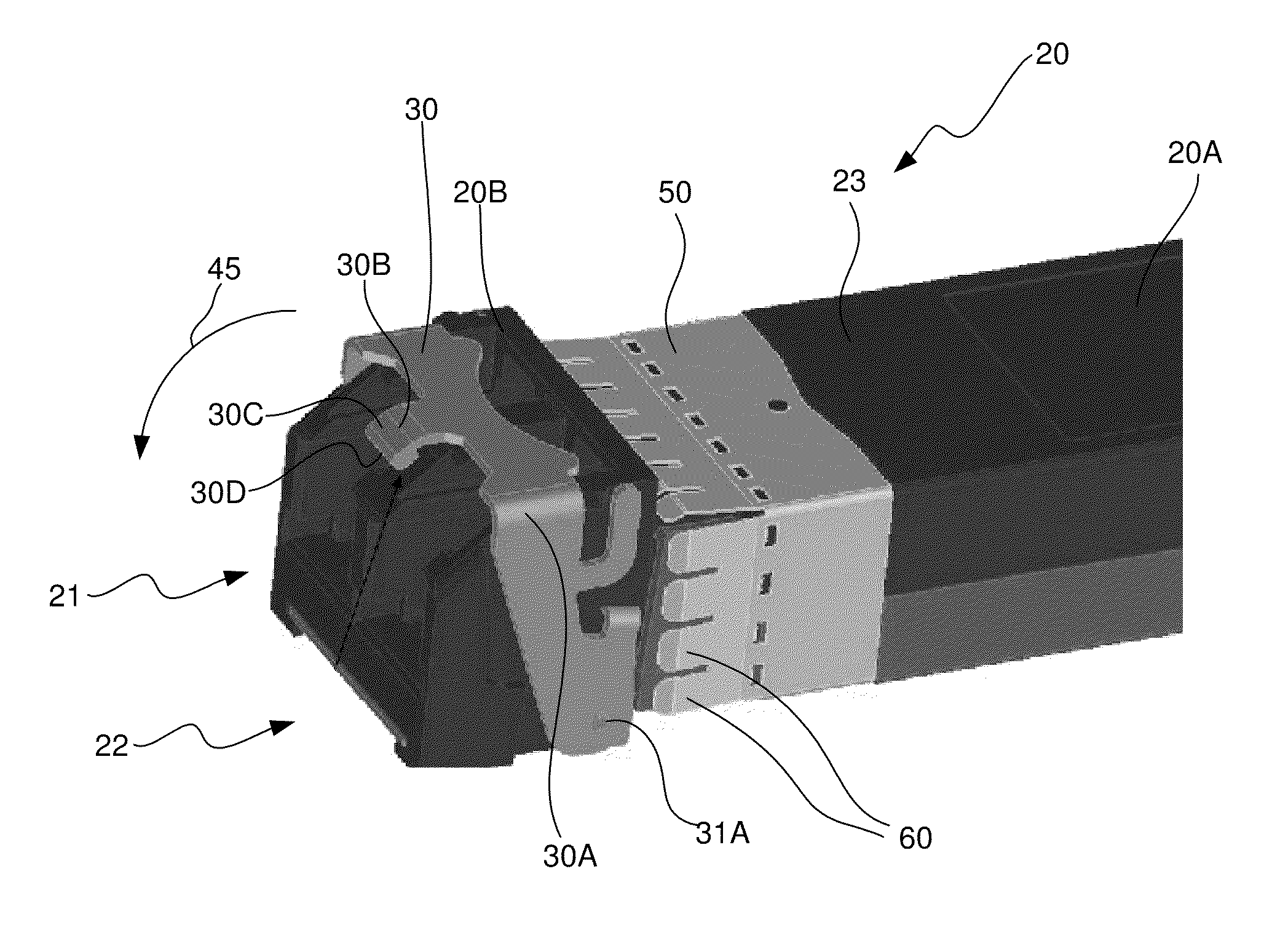
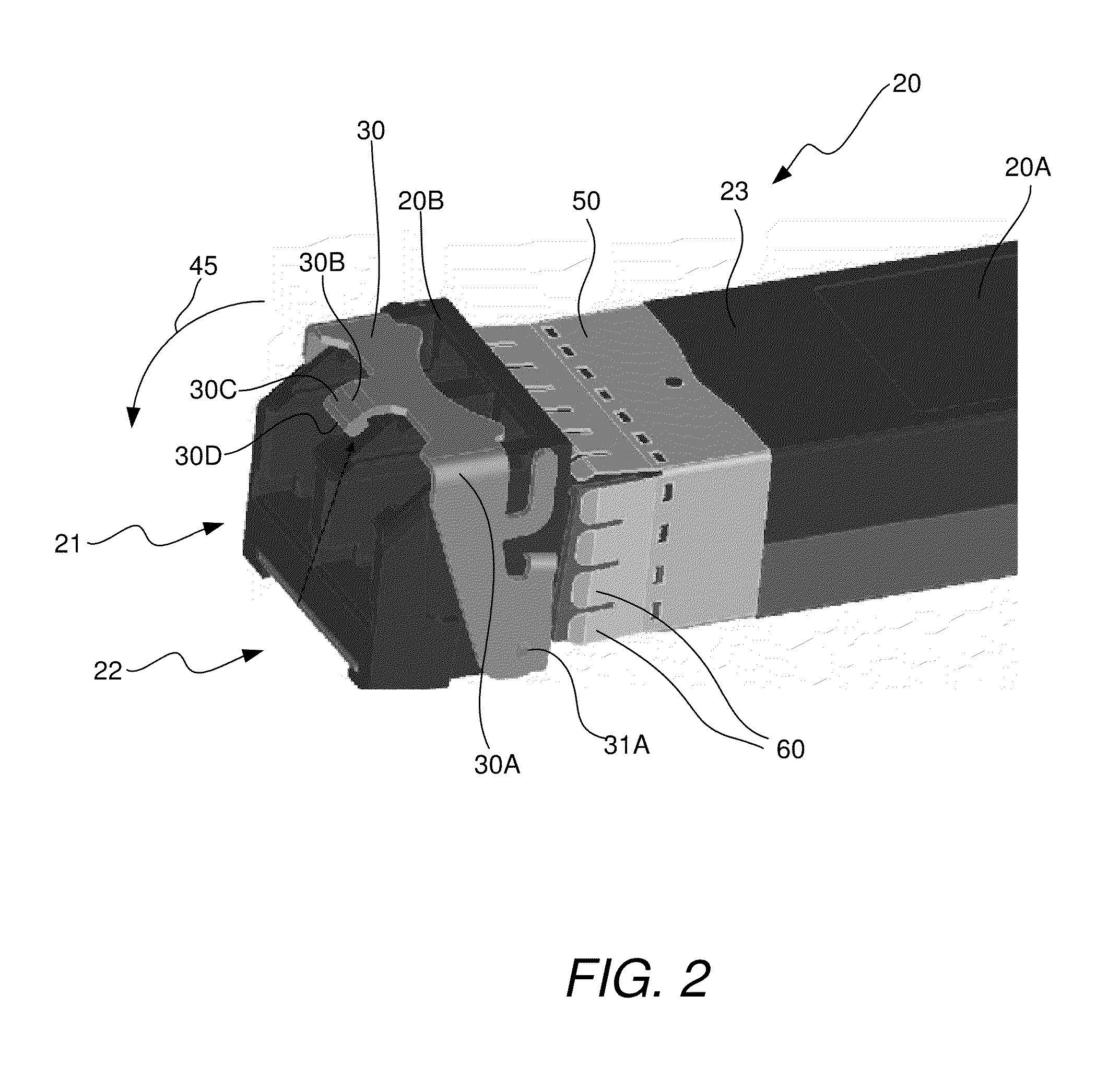
[0018]In accordance with various embodiments that will be described herein, an optical transceiver module is provided that has a pivoting bail latching mechanism that incorporates a cam locking configuration rather than a spring loading configuration used by most existing optical transceiver modules to move the latching mechanism to the locked position and maintain it in the locked position. The cam locking configuration provides the pivoting bail latching mechanism with stiffness and robustness in the locked position, thereby ensuring that forces exerted by the optical fiber cables will not result in mechanical misalignment between the cage and the transceiver module.

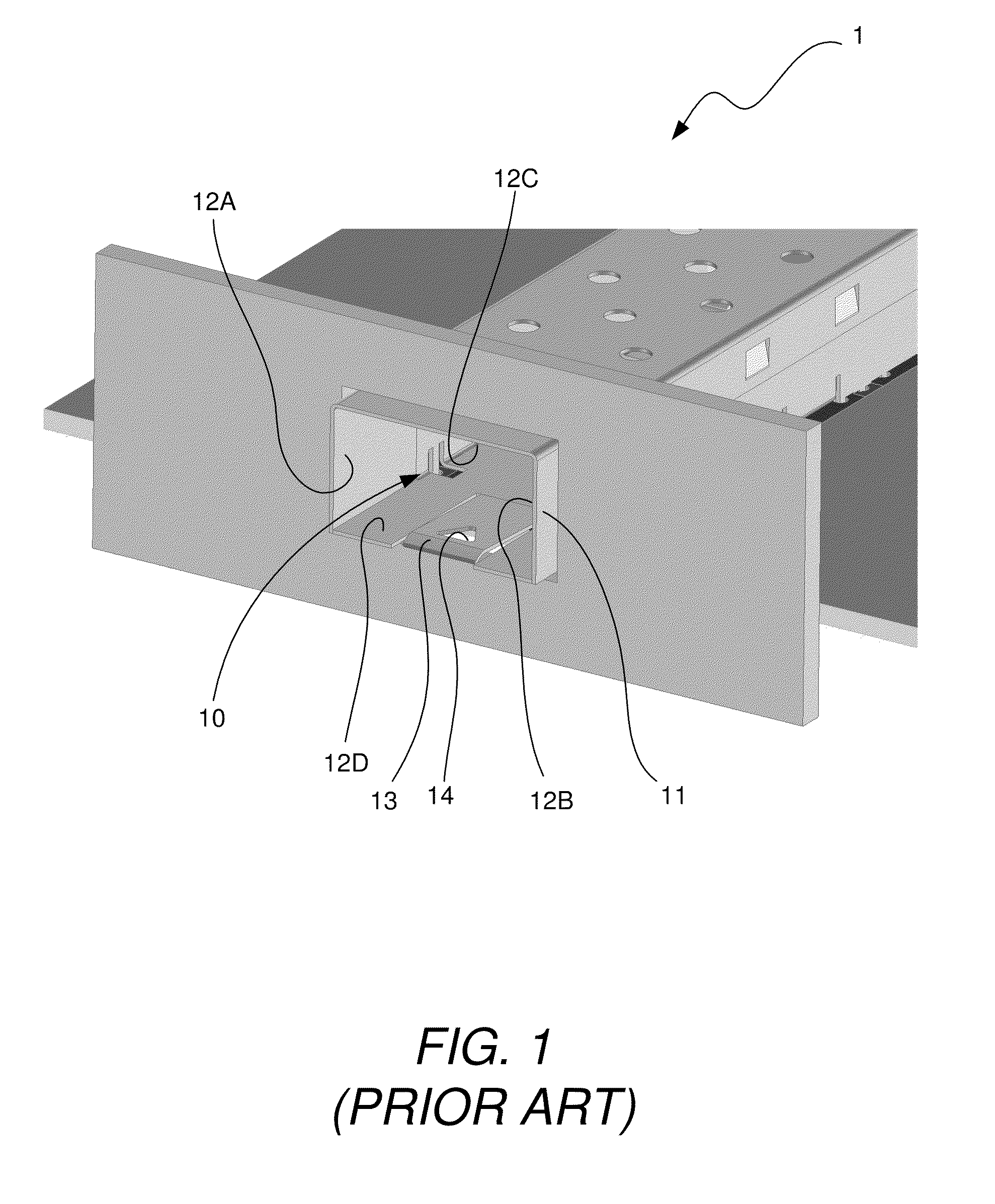
[0019]FIG. 1 illustrates a perspective view of a portion of the front side of a known rack 1 having a cage 10 secured thereto. The cage 10 is typically made of a flexible material, such as sheet metal for example, although other materials, such as die cast zinc are sometimes used. Typically, the rack 1 will contain man...


PUM


Abstract

An optical transceiver module is provided that has a pivoting bail latching mechanism that is extremely stiff and locks via a cam locking configuration rather than relying on spring-loading forces to bias the latching mechanism to and maintain the latching mechanism in a desired position. The stiffness of the pivoting bail latching mechanism provided by the cam locking configuration better ensures that forces exerted the transceiver module will not cause the transceiver module to come out of the cage while latched.

Description

TECHNICAL FIELD OF THE INVENTION[0001]The invention relates to optical transceiver modules. More particularly, the invention relates to an optical transceiver module having a latching bail mechanism that uses a cam lock configuration to lock the transceiver module to a cage.BACKGROUND OF THE INVENTION[0002]In optical communications networks, optical transceiver modules are used to transmit and receive optical signals over optical fibers. On the transmit side of a transceiver module, a light source (e.g., a laser diode) generates amplitude modulated optical signals that represent data, which are received by an optics system of the transceiver module and focused by the optics system into an end of a transmit optical fiber. The signals are then transmitted over the transmit fiber to a receiver node of the network. On the receive side of the transceiver module, the optics system of the transceiver module receives optical signals output from an end of a receive optical fiber and focuses ...

Claims


Application Information

Patent Timeline
13 Sep 2011
Publication
US8019226B2
IPC
H04B10/00
CPC
G02B6/4201; G02B6/4292
Inventors
MCCOLLOCH, LAURENCE R.