Split tip dialysis catheter

a dialysis catheter and split tip technology, applied in the field of catheters, can solve the problems of loss of catheter function, inefficient flow, clotting and fibrin sheath formation, etc., and achieve the effect of optimizing functionality

Inactive Publication Date: 2011-09-20
CR BARD INC
View PDF462 Cites 60 Cited by
  • Summary
  • Abstract
  • Description
  • Claims
  • Application Information

AI Technical Summary

Benefits of technology

[0008]In accordance with the present invention, a split tip dialysis catheter comprises an outer tube and an inner tube, wherein the two tubes can be arranged over at least a portion of their length in a coaxial configuration. The inner tube may be connected to the outer tube along a proximal segment, secured at the distal end of the outer tube, or both, but generally the inner tube will remain free to move relative to the outer tube to optimize functionality. In addition, the inner tube can be arranged to be removable from the catheter for replacement thereof. The inner and outer tubes can also be configured to have a differing geometry along their length.

Problems solved by technology

The primary problem in many dialysis catheters is that related to clotting and fibrin sheath formation.
Thrombus and fibrin can occlude distal tips of the catheter lumens, resulting in loss of catheter function when such an occlusion prevents blood flow.
A secondary problem is that related to the arterial lumen “sucking” against the vessel wall in which it resides.
This problem can occur if the arterial lumen ports become fully occluded by the patient's vasculature.
While such a scenario causes cleaned blood to flow directly toward the lumen that is under vacuum, line reversal in certain catheters can result in inefficient flow (high re-circulation).

Method used


Image

  • Split tip dialysis catheter
  • Split tip dialysis catheter
  • Split tip dialysis catheter

Examples


Embodiment Construction

[0029]The following detailed description illustrates the invention by way of example, not by way of limitation, the principles of the invention. This description will clearly enable one skilled in the art to make and use the invention, and describes several embodiments, adaptations, variations, alternatives and uses of the invention, including what we presently believe is the best mode of carrying out the invention.

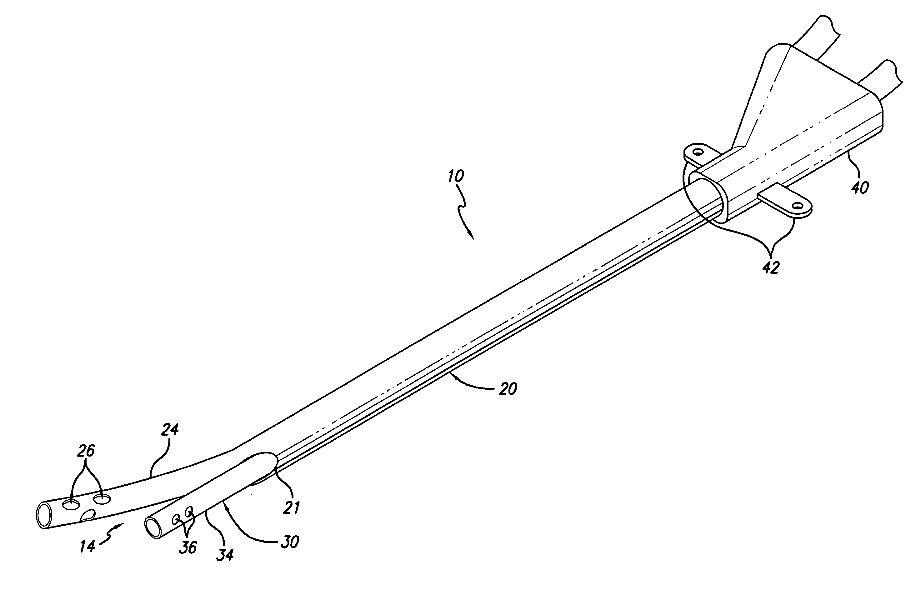
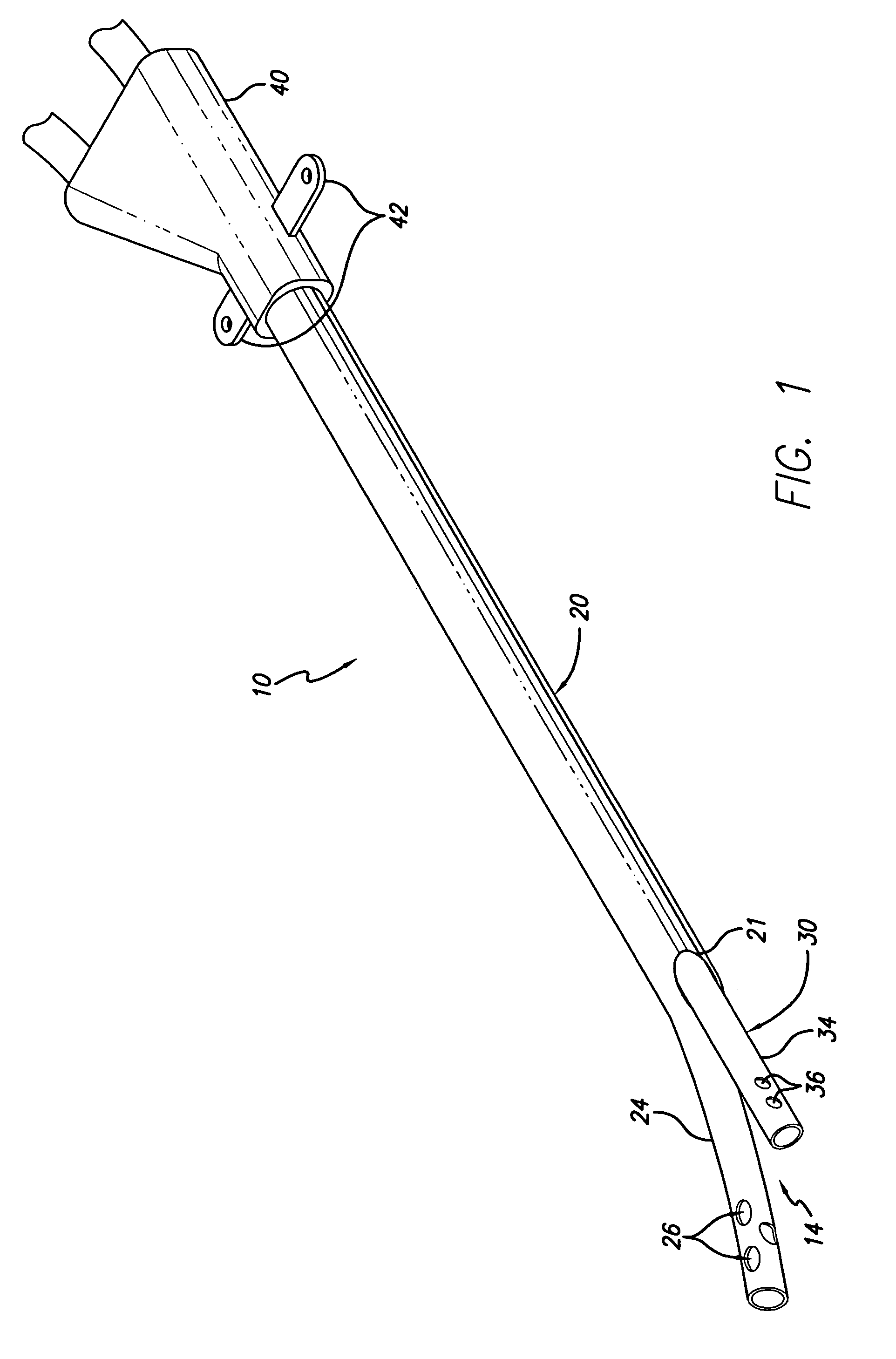
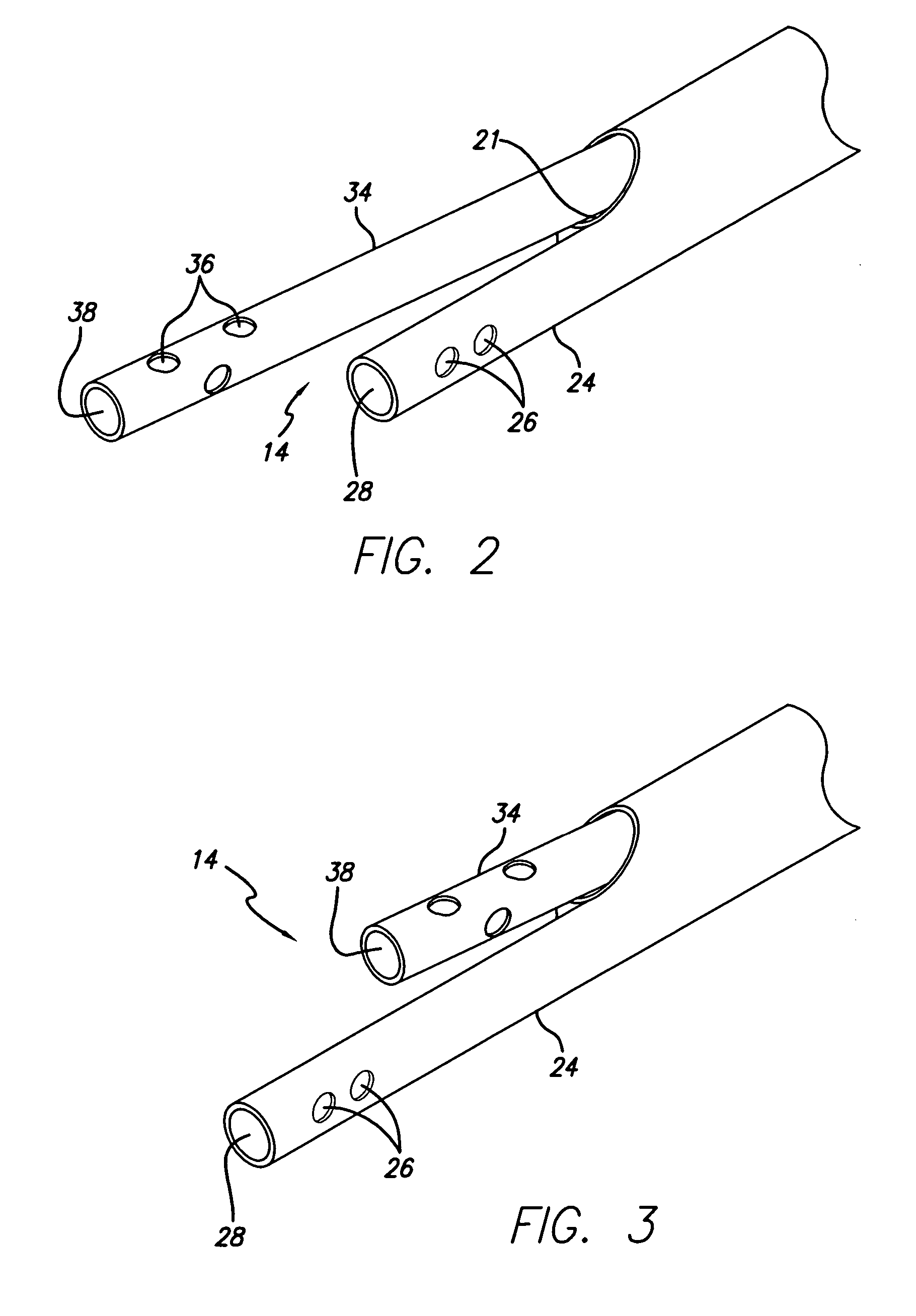
[0030]While a referenced use of the split-tip catheter of the present invention is in attaining short or long term vascular access for hemodialysis, apheresis and hemoperfusion treatments via the subclavian or internal jugular veins, other uses are certainly possible. For example, the split tip catheter of the present invention can be utilized in many applications suitable for a multi-lumen catheter, such as administration of intravenous fluids, blood products, drugs, and parenteral nutrition solutions as well as blood withdrawal.

[0031]When used for hemodialysis treatment...


PUM

PropertyMeasurementUnit
circumferenceaaaaaaaaaa
diameteraaaaaaaaaa
shapeaaaaaaaaaa

Abstract

A split tip dialysis catheter having an outer tube and an inner tube, the two tubes which can be arranged over at least a portion of their length in a coaxial configuration. The inner tube may be connected to the outer tube at a proximal bifurcation, secured at a distal end of the outer tube or both, but generally the inner tube will remain free to move relative to the outer tube to optimize functionality. In addition, the inner tube can be arranged to be removable from the catheter for replacement thereof.

Description

CROSS-REFERENCE TO RELATED APPLICATIONS[0001]This application is a continuation of application Ser. No. 10 / 072,788, filed Feb. 7, 2002, now U.S. Pat. No. 6,758,836, and expressly incorporates by reference the entirety thereof as if fully set forth herein.STATEMENT REGARDING FEDERALLY SPONSORED RESEARCH OR DEVELOPMENT[0002]Not applicable.REFERENCE TO A COMPACT DISK APPENDIX[0003]Not applicable.FIELD OF THE INVENTION[0004]The present invention relates to catheters and more particularly to catheters used for introduction and removal of fluids from a body.BACKGROUND OF THE INVENTION[0005]Multi-lumen catheters are used for a variety of applications where it is necessary to have two or more separate fluid pathways. One such application for a multi-lumen catheter is for use in hemodialysis. During hemodialysis, a dual-lumen catheter can be employed to simultaneously accommodate opposing blood flow. More specifically, one lumen aspirates blood from a blood vessel of a patient to a dialysis ...

Claims


Application Information

Patent Timeline
Patent Type & Authority Patents(United States)
IPC IPC(8): A61M1/00A61M3/00A61M39/02A61M1/14A61L29/00A61M1/36A61M25/00
CPCA61M1/3653A61M25/0032A61M2025/0031A61M1/3659A61M1/3661
Inventor ZAWACKI, JOHN A.
Owner CR BARD INC
Why Eureka
Try Eureka