Supercharge Your Innovation With Domain-Expert AI Agents!

Thermal pre-scanning of electric circuits using thermally-trimmable resistors

a technology of thermally-trimmable resistors and electric circuits, which is applied in the direction of resistors, non-adjustable resistors, analog circuit testing, etc., can solve the problems of limited precision, mechanical instability, and limited laser trimming range, and achieves difficult after-packaging. the effect of reducing the number of splicing and splicing

Inactive Publication Date: 2011-09-20
SENSORTECHNICS
View PDF7 Cites 5 Cited by
  • Summary
  • Abstract
  • Description
  • Claims
  • Application Information

AI Technical Summary

Benefits of technology

"The present invention provides a method to change the value of a thermally-trimmable resistor in a non-permanent way by raising its temperature to a level between room temperature and a trimming temperature. This allows for exploring the trimming range without actually trimming the resistor. The method involves applying a heat pulse to the resistor to raise its temperature and alter its resistance value, while observing the effect on other components in the circuit. The temporary change can be reversed by removing the heat source. The invention also provides a calibration step to determine the optimal temperature for trimming the resistor based on the pre-scan voltage or power."

Problems solved by technology

Manual trimpots are fully bidirectional over their entire range of resistance, but require manual operation, may have limited precision, and may be prone to mechanical instability.
Laser trimming has a more limited trim range, more limited bi-directionality, and is difficult to do after packaging.
However, they may also have constraints on bi-directionality of trimming.
For example, certain thermally-trimmable polysilicon resistors may be readily trimmed down (in the direction of decreasing resistance), from its as-manufactured resistance value (Ras-mfr), by tens of percent of Ras-mfr, but after such a trim-down, may have only limited trim-up (recovery) range.
In an in-circuit trimming application, limitations to full bi-directionality significantly constrain what can be done, and / or constrain trimming performance (e.g. speed, precision, range).
In the specific case of thermal trimming, if one doesn't know the final (optimal) trim target, it may be necessary for the adaptive trim to proceed more slowly, consuming more trimming time.

Method used


Image

  • Thermal pre-scanning of electric circuits using thermally-trimmable resistors
  • Thermal pre-scanning of electric circuits using thermally-trimmable resistors
  • Thermal pre-scanning of electric circuits using thermally-trimmable resistors

Examples


Embodiment Construction

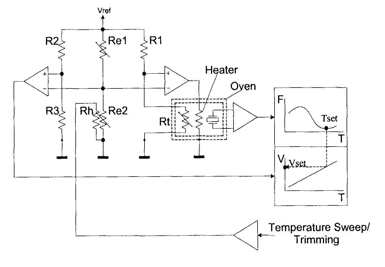
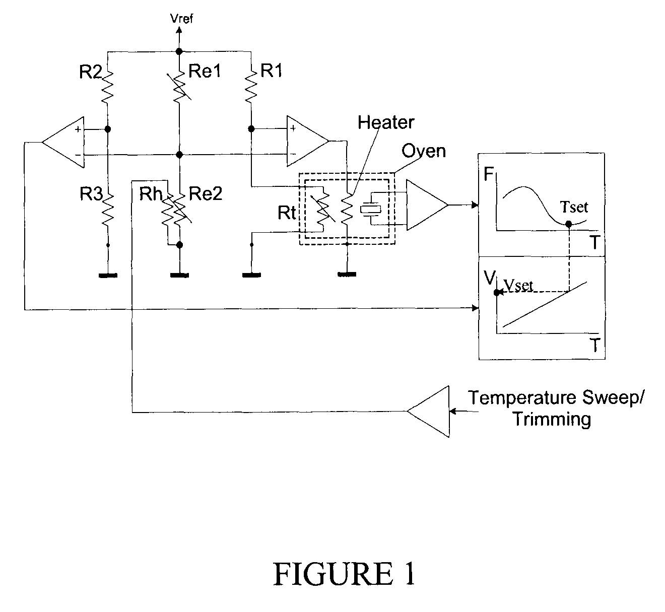
[0016]The specific case of thermal trimming provides an advantage over other trimming techniques having limited reversibility. The thermally-trimmable resistor may be electrically heated to temperatures significantly higher than room temperature or operating temperatures, without initiating significant thermal trimming. In such cases, if it has a significant non-zero temperature coefficient of resistance (TCR), then significant resistance changes may be available without committing to a trim. These reversible resistance changes may offer exploratory thermal pre-scanning of significant portions of the thermal trim range.

[0017]Thermally-trimmable resistors can offer this capability, exploratory thermal pre-scanning, to determine the desired trim-position, without committing the trim and irreversibly losing trim range. By exploratory pre-scanning, the approximate desired trim position can be ascertained, and then the trimming algorithm can take account of this position during the trim....


PUM


Abstract

There is described a method to change the value of a thermally-trimmable resistor in a non-permanent way by raising the temperature of the thermally-trimmable resistor to a level that is somewhere between room temperature and trimming temperature. By doing this, the trimming range that is available via true thermal trimming may be explored without actually trimming the value of the resistor. This is possible when the thermally-trimmable resistor, or a portion thereof, has an essentially non-zero temperature coefficient of resistance (TCR).

Description

CROSS-REFERENCE TO RELATED APPLICATIONS[0001]This application claims priority of U.S. Provisional Patent Application No. 60 / 784,785 filed on Mar. 23, 2006.TECHNICAL FIELD[0002]The invention relates to the trimming of a resistor or resistors, suitable for use at any level of the manufacturer-to-user chain. More specifically, it relates to trimming by resistive heating using electric current in the resistor itself or in an adjacent resistor.BACKGROUND OF THE INVENTION[0003]In the case of in-circuit trimming applications, a typical goal is to trim one or more resistors which are part of the circuit to adjust an overall circuit output which depends on those resistances. This circuit output may be any measurable quantity, but is typically translated into a voltage or current to be measured electrically. For simplicity, let us refer to such a circuit output as “Vout”. Usually, it is more convenient not to directly measure the resistance values of those trimmable resistors, because this ma...

Claims


Application Information

Patent Timeline
Patent Type & Authority Patents(United States)
IPC IPC(8): G01R27/08
CPCG01R19/32G01R31/2856H05K1/167H01C7/06H01C17/232H05K2203/1105H05K2203/171G01R31/316H01C17/265
Inventor GRUDIN, OLEGLANDSBERGER, LESLIE M.FROLOV, GENNADIY
Owner SENSORTECHNICS
Features
  • R&D
  • Intellectual Property
  • Life Sciences
  • Materials
  • Tech Scout
  • Unparalleled Data Quality
  • Higher Quality Content
  • 60% Fewer Hallucinations
Learn More