

Achromatic optical system for beam shaping
a beam shaping and optical system technology, applied in optics, telescopes, instruments, etc., can solve the problems of optimum one, inability to meet the requirements of high-power applications, and obvious loss of laser energy
Inactive Publication Date: 2011-09-20
MOLECULAR TECH
View PDF19 Cites 12 Cited by
- Summary
- Abstract
- Description
- Claims
- Application Information
AI Technical Summary
Benefits of technology
"The patent describes an achromatic refractive field mapping system that can transform the intensity distribution of input light to another intensity distribution of output light. This system has zero or negligible wave aberration, which ensures equal path lengths for the rays of input beam at each wavelength in a certain spectral range. The system can be used in various applications such as telescopes, collimators, and objectives. The lens groups of the system can be made of different lenses with different characteristics of dispersion, and the system can provide uniform intensity distribution or other intensity distributions as required. The lens groups can also be made movable along the optical axis for fine adjustments in real applications."
Problems solved by technology
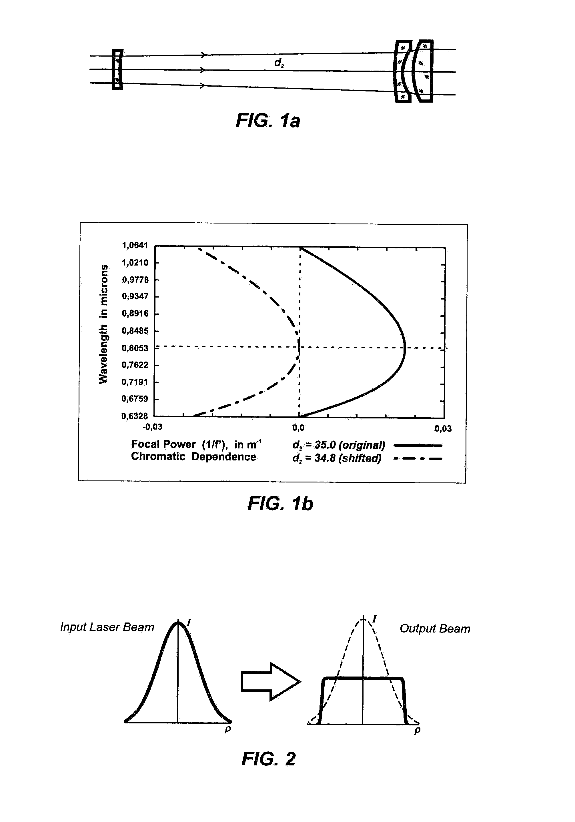
From one side, this Gaussian profile provides high energy concentration, however, from another side for many industrial applications it is not an optimum one because of non-uniform intensity distribution within the laser beam.
Losing of laser energy is an evident disadvantage of this solution.
It is unacceptable in high power applications.
An obvious disadvantage of this integration approach is using of complicated, difficult to produce and expensive array optical elements.
In case of applying the DOE the range of applications can be limited because of unaccepted diffraction losses.
Using diffractive optical elements in field mapping optical systems is limited by unaccepted diffraction losses that are critical in high power applications.
The solution based on applying of mirrors suffers from complexity and expensiveness of their manufacturing due to off-axis design, difficulties of shop testing and proper assembling.
The serious problem of conventional refractive field mapping systems is that these two basic design conditions can be fulfilled for a certain wavelength only.
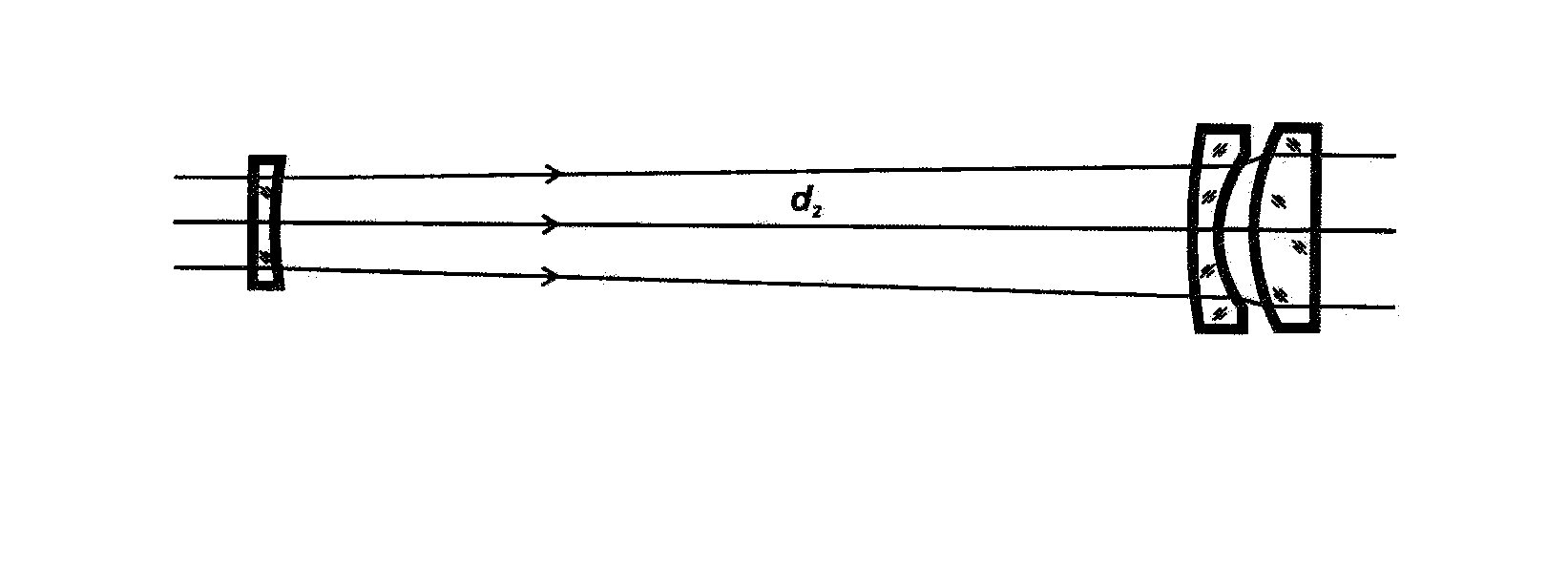
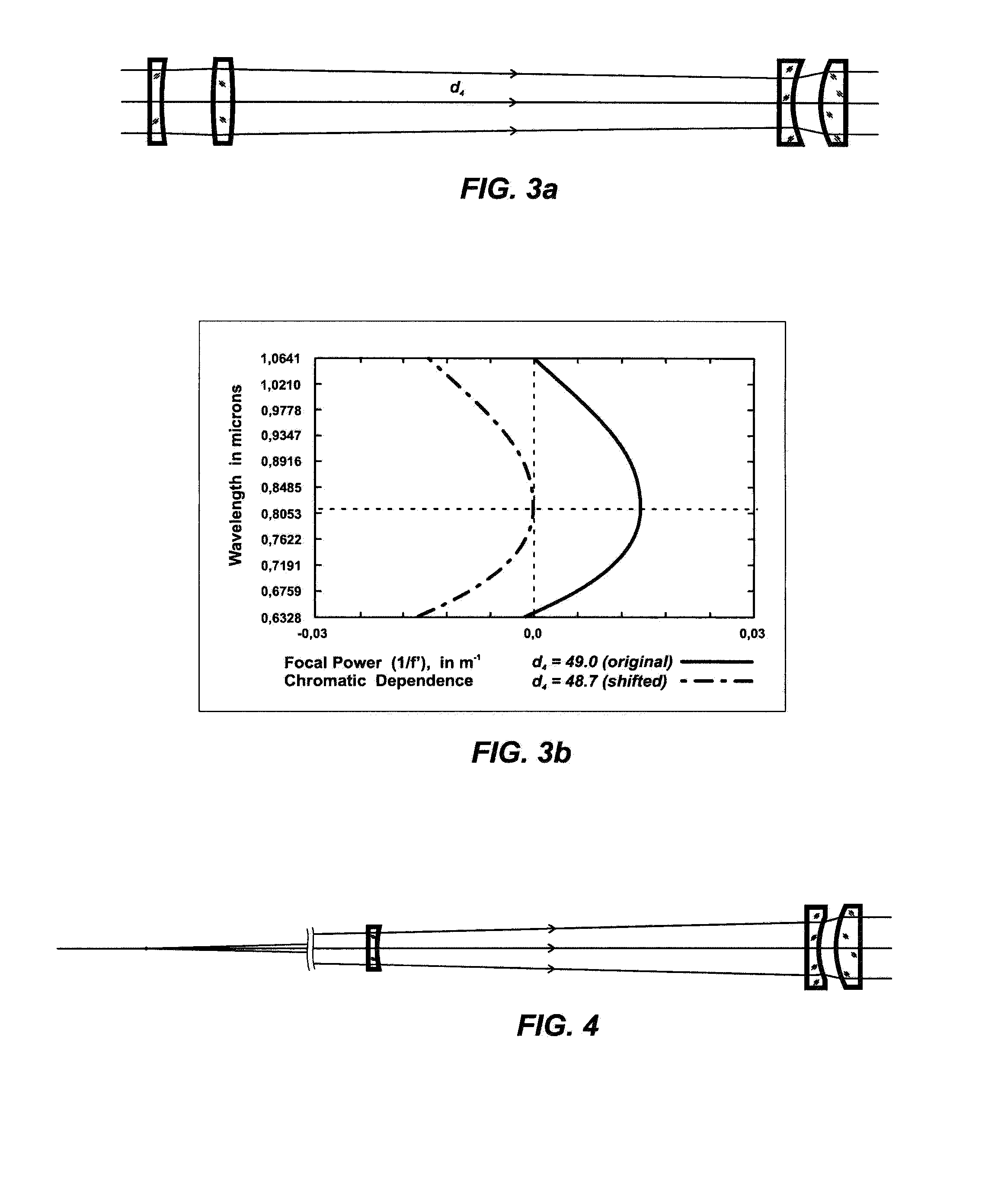
When switching to another working wavelength and trying to provide uniform intensity distribution it would be necessary to change some parameters of known refractive field mapping systems (for example, distance between lens groups of a telescope), in this case, however, it is impossible to keep simultaneously zero wave aberration and, hence, avoid interference effects destroying the uniformity of the intensity profile.
Evidently, this way leads to increasing of components of a complete optical system that reduces its transmission, makes it more expensive, complicated and, hence, less reliable, more sensitive to misalignments, difficult to use in practice.
Thus, the known field mapping solutions cannot provide an efficient, reliable, easy to use optical system for a simultaneous beam profile transformation for two wavelengths or a range of wavelengths.
Important disadvantage of conventional beam mapping systems is that they have afocal design only, hence both input and output laser beam have to be collimated.
Thus, from the point of view real conditions of manufacturing and using in real laser applications the conventional solutions aren't optimal.
Method used
View moreImage
Smart ImageViewing Examples

Examples
embodiment 3
the present invention provides combining in a sole optical system the functions of the laser beam collimation as well as beam shaping.
Login to View More PUM
 Abstract
An achromatic refractive beam shaping optical system that transforms the intensity distribution of a light beam, preferably provides transformation of a beam which intensity distribution described by Gaussian function to a beam of uniform intensity. The system consists of at least two lens groups, one of lens groups is made from at least two lenses having different characteristics, of spectral dispersion, thus achromatic for a certain spectral range optical design providing zero or negligible for practical applications wave aberration is realized. By choosing parameters of lens groups the system can be realized as a telescope of Galilean or Keplerian type, or as a collimator, or as an objective lens. To provide adjustment features one lens group of the system is movable along the optical axis.
Description
FIELD OF INVENTION[0001]The present invention relates to the field of optics; in particular to optical systems for beam shaping being intended to transform intensity distribution of light beam. The invention can be applied in laser optics.BACKGROUND TO THE INVENTION[0002]Lasers are widely applied in various applications in industry and their effective using is very important. Typically the intensity profile of laser sources is described by Gaussian function provided by physics of creating the laser radiation. From one side, this Gaussian profile provides high energy concentration, however, from another side for many industrial applications it is not an optimum one because of non-uniform intensity distribution within the laser beam. In such applications like welding, soldering, annealing, illumination of spatial light modulators, holography a homogenized laser beam is most preferable from the point of view of saving the energy and providing the same conditions of material treatment i...
Claims
Login to View More Application Information
Patent Timeline
 Patent Type & AuthorityPatents(United States)
IPC IPC(8): G02B9/00
CPCG02B27/0927
InventorLASKIN, ALEXANDER
OwnerMOLECULAR TECH