Indicating fastener loading

a technology of fasteners and indicators, applied in the direction of screws, instruments, force/torque/work measurement apparatus, etc., can solve the problems of increasing load, reducing the range of movement, reducing the degree of clearance of the first lever, and achieving the proper fastener loading (tension) and maintaining this loading once the system is placed in servi

Active Publication Date: 2011-09-27
VALLEY FORGE & BOLT MFG
View PDF26 Cites 13 Cited by
  • Summary
  • Abstract
  • Description
  • Claims
  • Application Information

AI Technical Summary

Benefits of technology

[0035]In some implementations, the fastener or bolt includes a head and a shank and central bore defined in the head and shank. A datum rod is anchored within the central bore in the fastener. The fastener head defines a reference surface and a load indicator indexing interface. A free end of the datum rod moves relative to a reference surface on the fastener head upon loading and elongation of the fastener. In some cases, a portion of the reference surface also serves as the load indicator indexing surface. The load indicator indexing interface on the fastener head and the bolt indexing interface on the load indicator provides for alignment and / or temporary mounting of the load indicator atop the fastener.
[0046]In some cases, the load indicator is provided with seals around any housing openings to prevent intrusion of moistures.
[0050]In some implementations, a light source is provided adjacent the visual scale and pointer to allow for low light readings. In some cases, the light source is an LED powered by a battery. In some cases, the light source is a phosphorescent coating on at least one of the pointer and the visual scale.
[0053]In some implementations, the load indicator includes a magnet to help maintain the load indicator in indexed engagement with the fastener head. In some case, the magnet forms part of the fastener indexing interface.
[0058]Multiple levers within the load indicator may cooperate to indicate the load on the fastener by amplification of the elongation experienced by the fastener. A multi-lever design may provide a visible range of pointer movement even with a significantly reduced indicator diameter and a reduced indicator depth.
[0062]Use of two levers to shift part of the amplified response to the second lever reduces the range of movement of the first lever and the degree of clearance required for the first lever. For in-fastener embodiments, this significantly reduces the dimensions of the section of the fastener bore required to accommodate the amplified lever response. Additional advantages afforded by the present invention include increased sensitivity of the load indicator, a reduction in the overall length of load indicator and in the depth of the bore.

Problems solved by technology

In many applications, achieving the proper fastener loading (tension) and maintaining this loading once the system is placed in service can be problematic.
Monitoring the load on a fastener during installation and service can be equally problematic.
As a fastener is continually tightened, the load increases until the fastener ultimately yields, breaks, or its integrity is otherwise compromised.
Thus, overtightening a fastener can lead to catastrophic failures.
Conversely, fasteners typically experience some loss of tension in service due to, for example, a variety of in-service occurrences including: relaxation (thread embodiment), vibration loosening, compressive deformation in the joint or flange, temperature expansion or contraction, etc.
Loss of tension from these occurrences can cause misalignment or premature wear in a bolted assembly, leakage (in applications where the fastener is used for sealing), or catastrophic joint failure due to excessively high loads on other members of the assembly.
Determining the tensile load of conventional fastener often entails cumbersome methods to check the tightness of each bolt, such as loosening and re-tighten all of the fasteners regardless of whether such re-tightening is needed.
The retorquing (i.e. tightening) of a fastener, however, induces wear and strain in the fastener system.
Additionally, corrosion, friction, variations in nut condition, and the like can cause variations in torque values and introduce error into tensile load measurements.
Other proposed methods often require costly tools or readers or special training.
For example, electronic or ultrasonic methods for determining tensile loads require experienced operators, expensive equipment, clean surfaces and records of pre-installation test values for each bolt or stud.
In addition, such systems may be adversely affected by shock and other extreme conditions.

Method used


Image

  • Indicating fastener loading
  • Indicating fastener loading
  • Indicating fastener loading

Examples


Embodiment Construction

[0076]The following description is of example implementations of the invention only, and is not intended to limit the scope, applicability or configuration of the invention. As will become apparent, various changes may be made in the function and arrangement of the elements described in these implementations without departing from the scope of the invention as set forth herein.

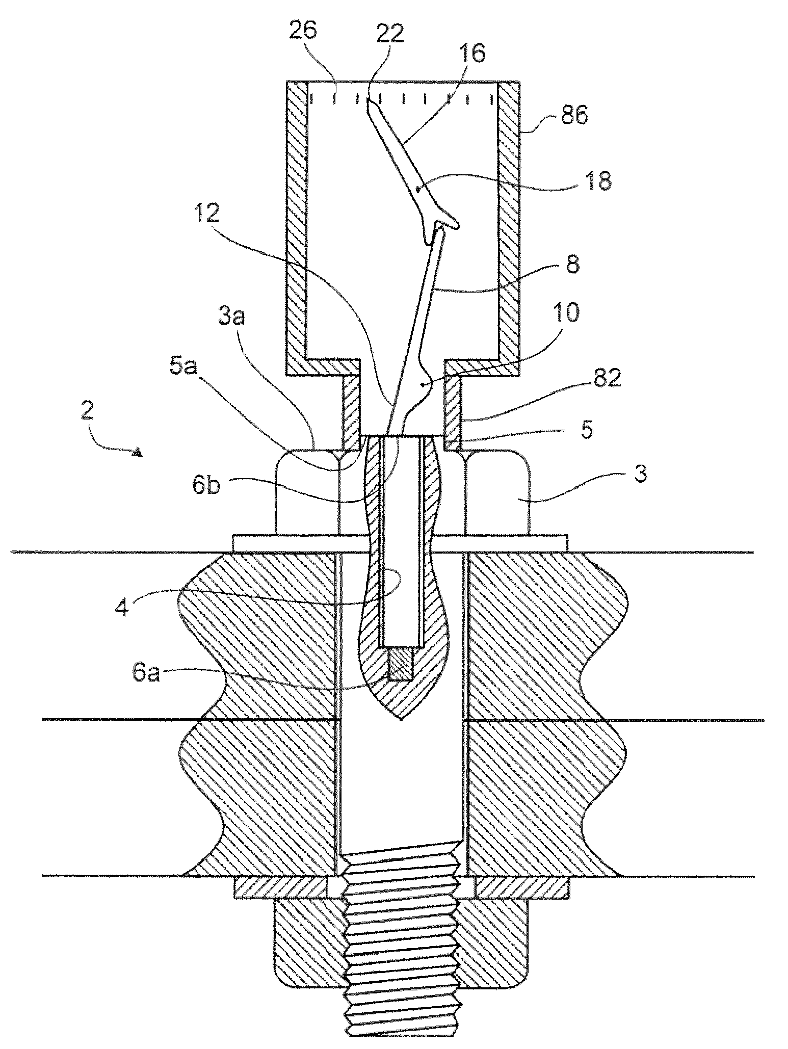
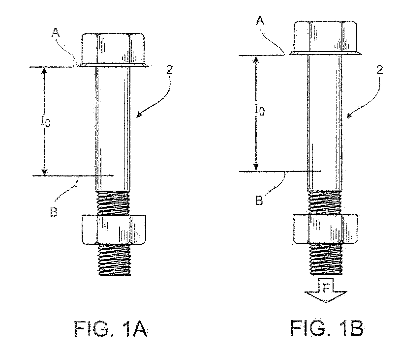
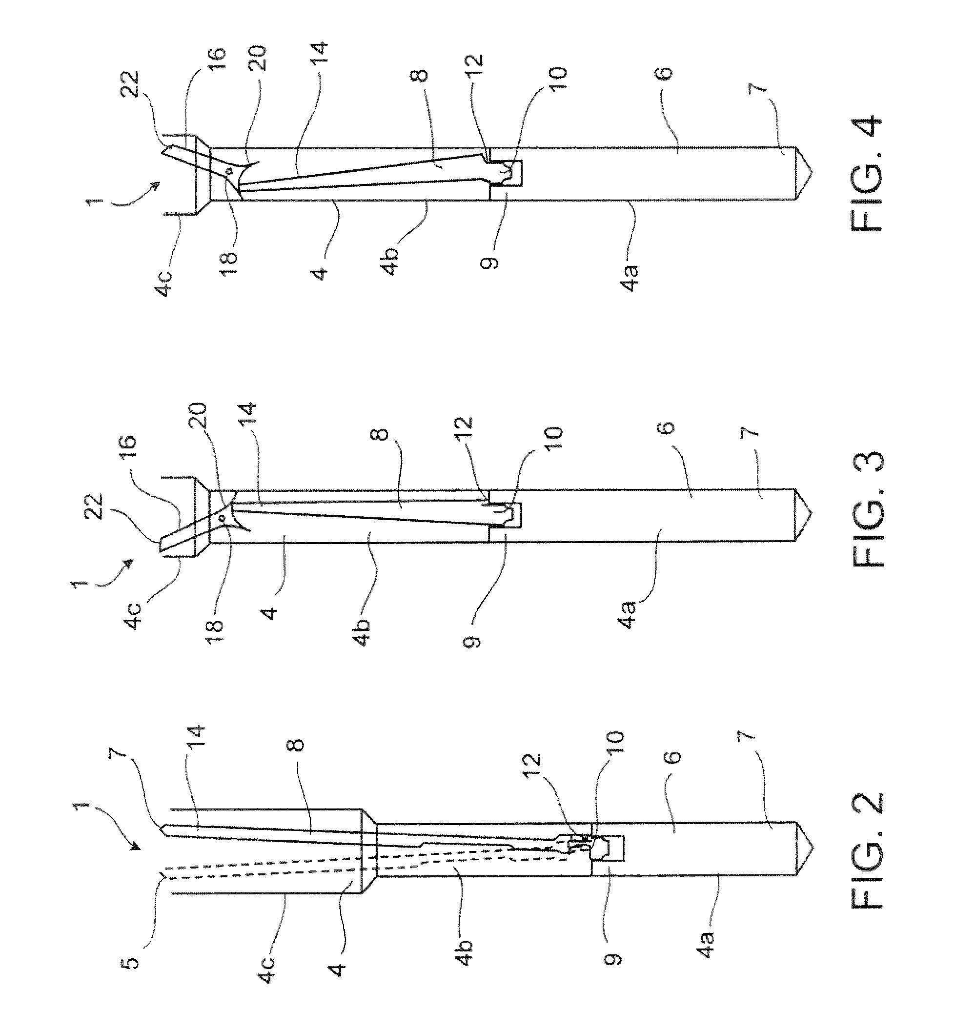
[0077]In accordance with various aspects of the invention, a load indicator includes a housing or “cartridge” housing or connecting various indicator elements. The housing or cartridge may be temporarily mounted to the head of a fastener or may be permanently mounted within a fastener bore to measure the tensile load of the fastener. The cartridge includes first and second moveable members or “levers” that interact to provide an amplified response to the elongation of the fastener to provide a visual indication along a visual scale.

[0078]While described here in the example context of a bolt, it should be appre...


PUM


Abstract

An amplified indication of the elongation of a fastener is provided for determining instantaneous loading conditions of a fastener. A load indicator is couplable to a fastener for instantaneous load measurement and includes a housing defining a fastener interface configured to removably couple the housing to a fastener. A moveable datum probe extends from the housing in contact with a datum rod anchored within an internal bore of the fastener. A first lever is pivotally mounted within the housing and is moveable in response to displacement of the datum probe. A load display indicates a degree of loading of a fastener as a function of displacement of the datum probe. A second lever can be used to further amplify the reading from the displacement of the datum probe. An inclined visual scale and a multi-faceted lens allows for viewing of loading values from multiple directions or angles.

Description

CROSS-REFERENCE TO RELATED APPLICATIONS[0001]This application is a continuation-in-part of U.S. application Ser. No. 11 / 467,011 filed on Aug. 24, 2006, which is incorporated herein by reference in its entirety.FIELD OF INVENTION[0002]This invention generally relates to load indicating, and more particularly, to visually representing and reading loading of fasteners and fastenings.BACKGROUND OF THE INVENTION[0003]Fasteners are used in a wide variety of applications, such as mills, motors, railroad tracks, flange assemblies, petrochemical lines, foundations, drag lines, power turbines and studs on cranes and tractors. In many applications, achieving the proper fastener loading (tension) and maintaining this loading once the system is placed in service can be problematic. Monitoring the load on a fastener during installation and service can be equally problematic.[0004]As a fastener is continually tightened, the load increases until the fastener ultimately yields, breaks, or its integr...

Claims


Application Information

Patent Timeline
Patent Type & Authority Patents(United States)
IPC IPC(8): F16B31/02
CPCF16B31/025G01L5/24
Inventor CLARKE, RONALD C.
Owner VALLEY FORGE & BOLT MFG
Why Eureka
Try Eureka