
Ophthalmologic apparatus for imaging an eye by optical coherence tomography

a technology of optical coherence tomography and ophthalmologic equipment, which is applied in the field of ophthalmologic equipment, can solve the problems of easy wear, sensitive to mechanical effects, and inability to perform examinations as often as desirable, and achieve the effect of rapid and real-time control treatmen

Inactive Publication Date: 2011-09-27
MIMOSA
View PDF16 Cites 21 Cited by
  • Summary
  • Abstract
  • Description
  • Claims
  • Application Information

AI Technical Summary

Benefits of technology

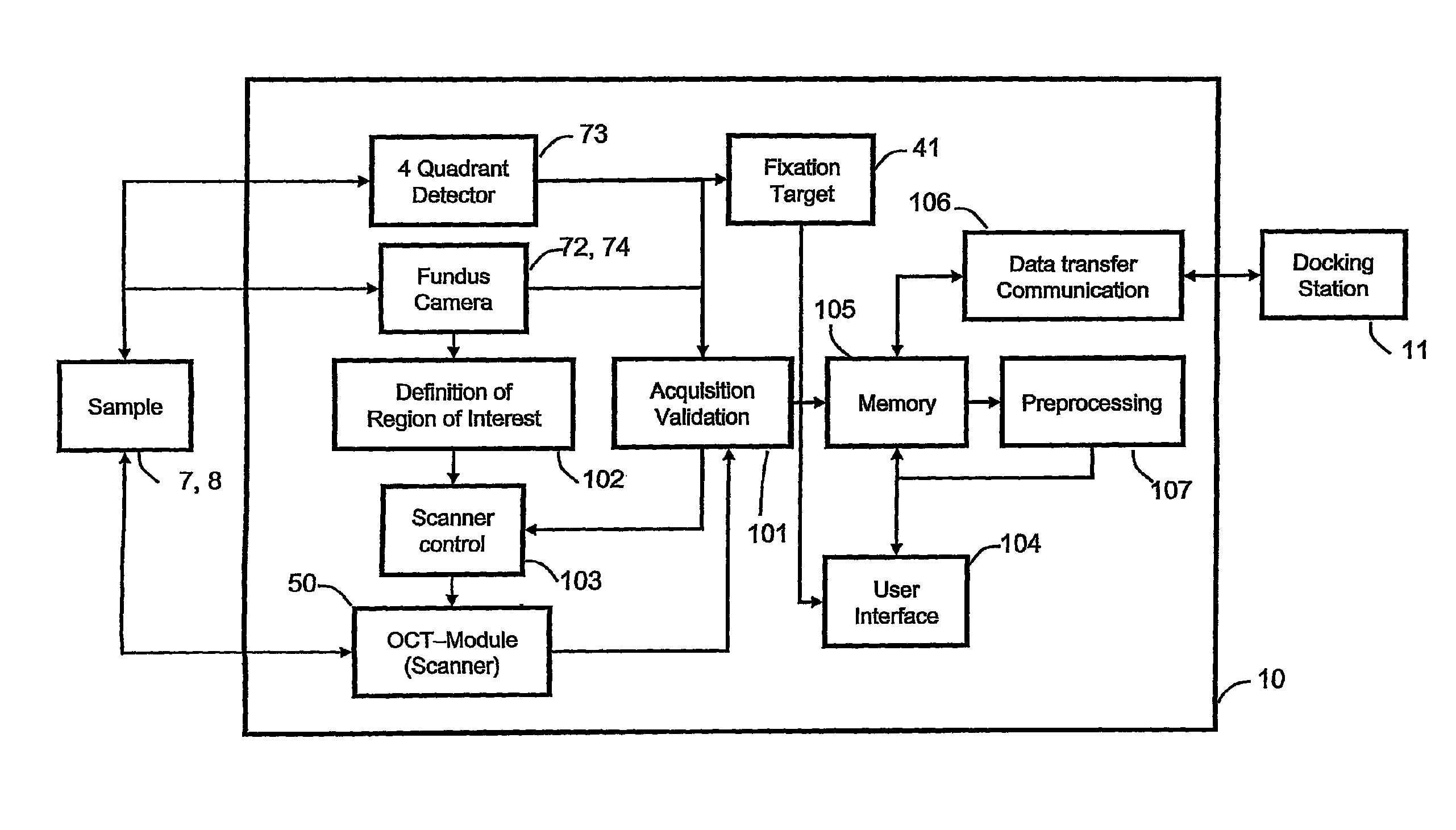
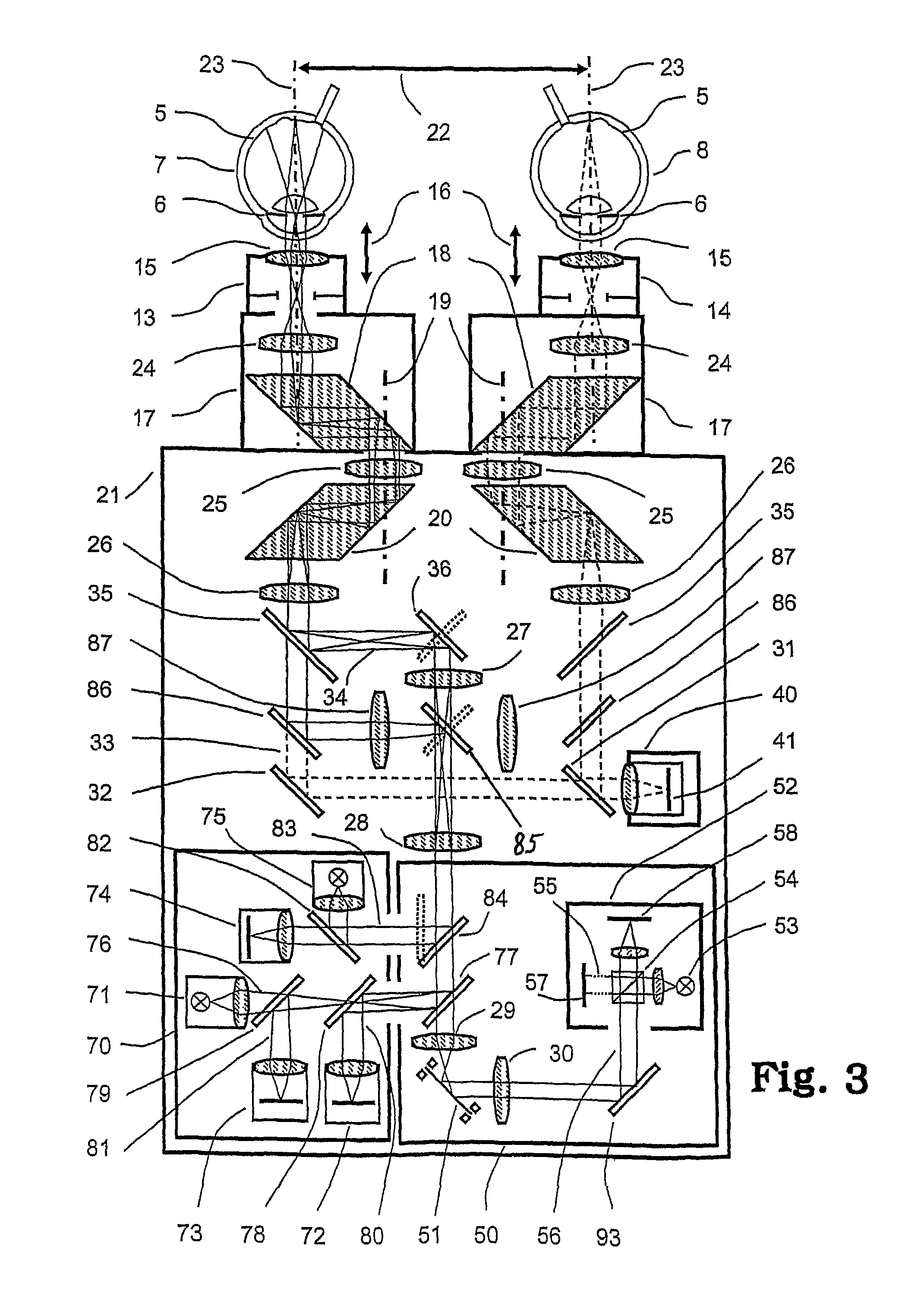
"The invention proposes an ophthalmic apparatus with reduced adjustment demands, allowing for patient self-examination. The device uses a fundus camera to accurately position the eye and direct the OCT unit to a specific area of interest. The apparatus has a binocular housing for easy positioning and a mechanism for automatically aligning the eyes. The device can be adjusted to the patient's viewing capabilities and interpupillary distance, and can also have an external device for therapeutic purposes. The technical effects include improved accuracy and efficiency in ophthalmic examination and treatment."

Problems solved by technology

Obviously, this provision requires fast reacting and exact working mechanical means, hence is prone to wear and sensitive to mechanical effects (shock, vibration).
A disadvantage of the known apparatuses is that they have to be adjusted to each patient and that the ophthalmologist or a well instructed expert has each time to search for the region of interest and to perform the corresponding adjustments manually.
However, due to the fact that the patient has to visit a professional therefor, it was impossible to perform the examinations as often as desirable.
Generally, due to irregularities of the eye, this procedure has to be performed more than once to achieve an exact aiming of the device.

Method used


Image

  • Ophthalmologic apparatus for imaging an eye by optical coherence tomography
  • Ophthalmologic apparatus for imaging an eye by optical coherence tomography
  • Ophthalmologic apparatus for imaging an eye by optical coherence tomography

Examples


Embodiment Construction

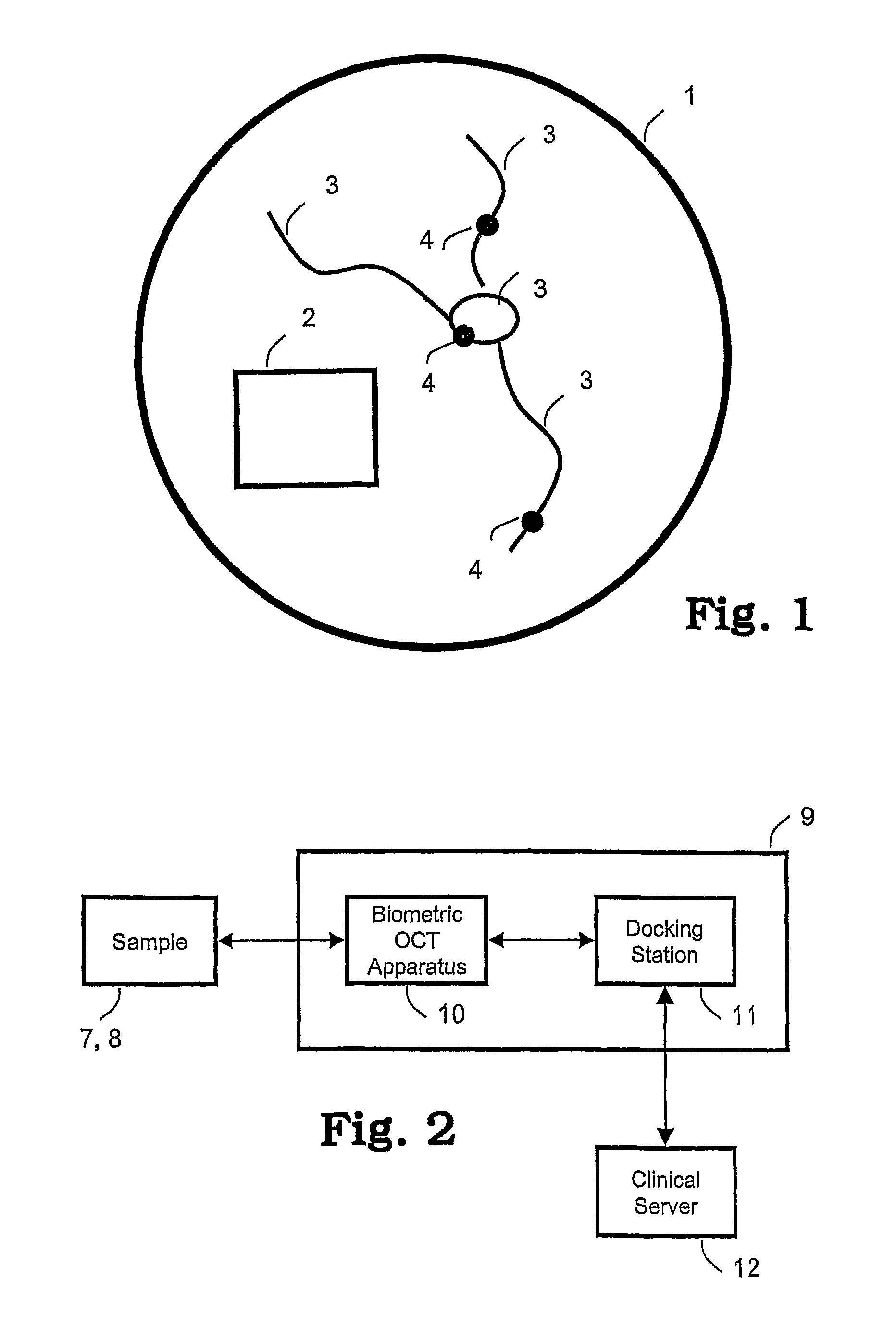
[0034]FIG. 1 illustrates the image taken by a fundus camera in a schematized style. The image 1 comprises details of the eye's retina. Within the biometric features 3 of the retina, markers 4 can be defined which are linked be the biometric features 3. Relative to the markers 4, the region of interest (ROI) 2 is defined. Of course, it is possible to have more than one single ROI defined, and another number of markers can be used.

[0035]The overall architecture of a biometric OCT appliance according to the invention is depicted in FIG. 2. The system comprises the OCT appliance 9, a clinical server 12, and for the sake of completeness, the “sample”, i.e. the eyes 7, 8 to be scrutinized. The OCT appliance is composed of the ophthalmic apparatus (OCT apparatus) 10 and a docking station 11. The docking station 11 serves as primary personal patient-data input system, data memory, performs data postprocessing, recharges the accumulators of the OCT apparatus 10 and holds the OCT apparatus be...


PUM


Abstract

An OCT appliance (optical coherence tomography appliance) comprises an OCT module and a camera for observing the fundus of an eye. By recognizing characteristic features (biometric features), the means defining the region observed by the OCT module, in particular the scanner of the OCT module, is adjusted so that a predefined region of interest is imaged by the OCT module. In preferred embodiments, the apparatus is apt to be operated by a patient himself, and the data are transferred to a clinical server so that a more frequent, hence closer observation of the eyes of the patient is possible.

Description

CROSS REFERENCE TO RELATED APPLICATIONS[0001]The present application is a 35 U.S.C. §371 National Phase conversion of PCT / CH2008 / 000067, filed Feb. 18, 2008, which claims benefit of European Application No. 07405056.8, filed Feb. 23, 2007, the disclosure of which is incorporated herein by reference. The PCT International Application was published in the English language.BACKGROUND OF THE INVENTION[0002]The present invention relates to an ophthalmologic apparatus, according to the preamble of claim 1.[0003]Optical coherence tomography (OCT) is an established noninvasive, noncontact imaging technology which can image eye structures, and more importantly high resolution cross sectional images of the retina not only on the surface, but also up to certain depth are produced. Basics of this method is available on the internet (e.g. in the Wikipedia).[0004]An apparatus and a method for diagnosing and monitoring eye diseases by OCT is described in U.S. Pat. No. 6,293,674. U.S. Pat. No. 6,32...

Claims


Application Information

Patent Timeline
Patent Type & Authority Patents(United States)
IPC IPC(8): A61B3/14A61B3/10
CPCA61B3/102A61B3/12A61B3/1208A61B3/1225
Inventor MALOCA, PETERHAROUD, KARIMSCHNELL, URBAN
Owner MIMOSA
Learn More