Eureka AIR delivers breakthrough ideas for toughest innovation challenges, trusted by R&D personnel around the world.

Circuit and method to improve energy harvesting efficiency in piezoelectric harvesters

a piezoelectric harvester and energy harvesting technology, applied in piezoelectric/electrostrictive/magnetostrictive devices, piezoelectric/electrostriction/magnetostriction machines, electrical equipment, etc., can solve the problems of limiting the maximum power that can be extracted using the full-bridge rectifier, and the majority of the available power of the harvester b>4/b> is just wasted, so as to achieve efficient energy management

Inactive Publication Date: 2011-09-27
MASSACHUSETTS INST OF TECH
View PDF10 Cites 43 Cited by
  • Summary
  • Abstract
  • Description
  • Claims
  • Application Information

AI Technical Summary

Problems solved by technology

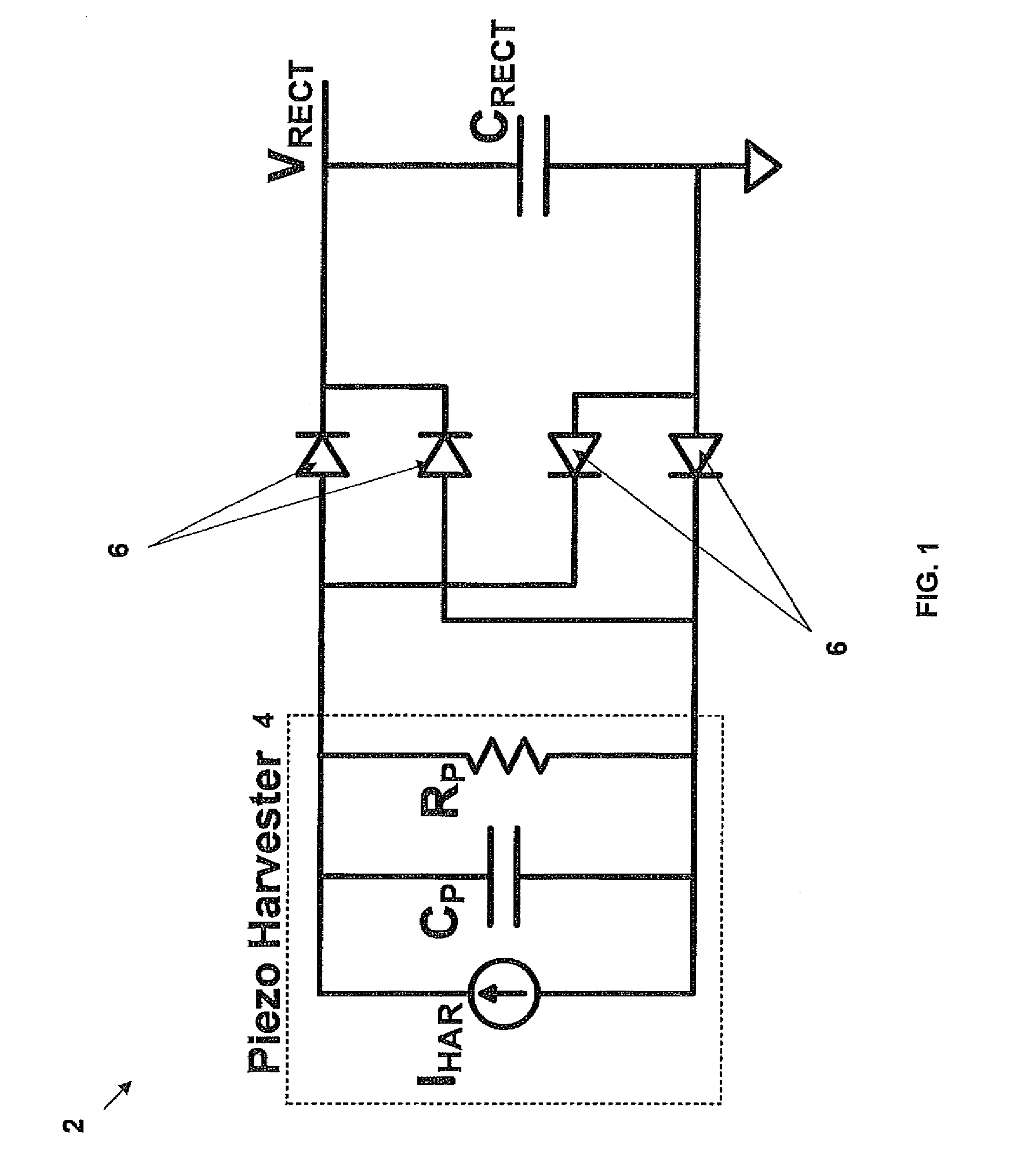
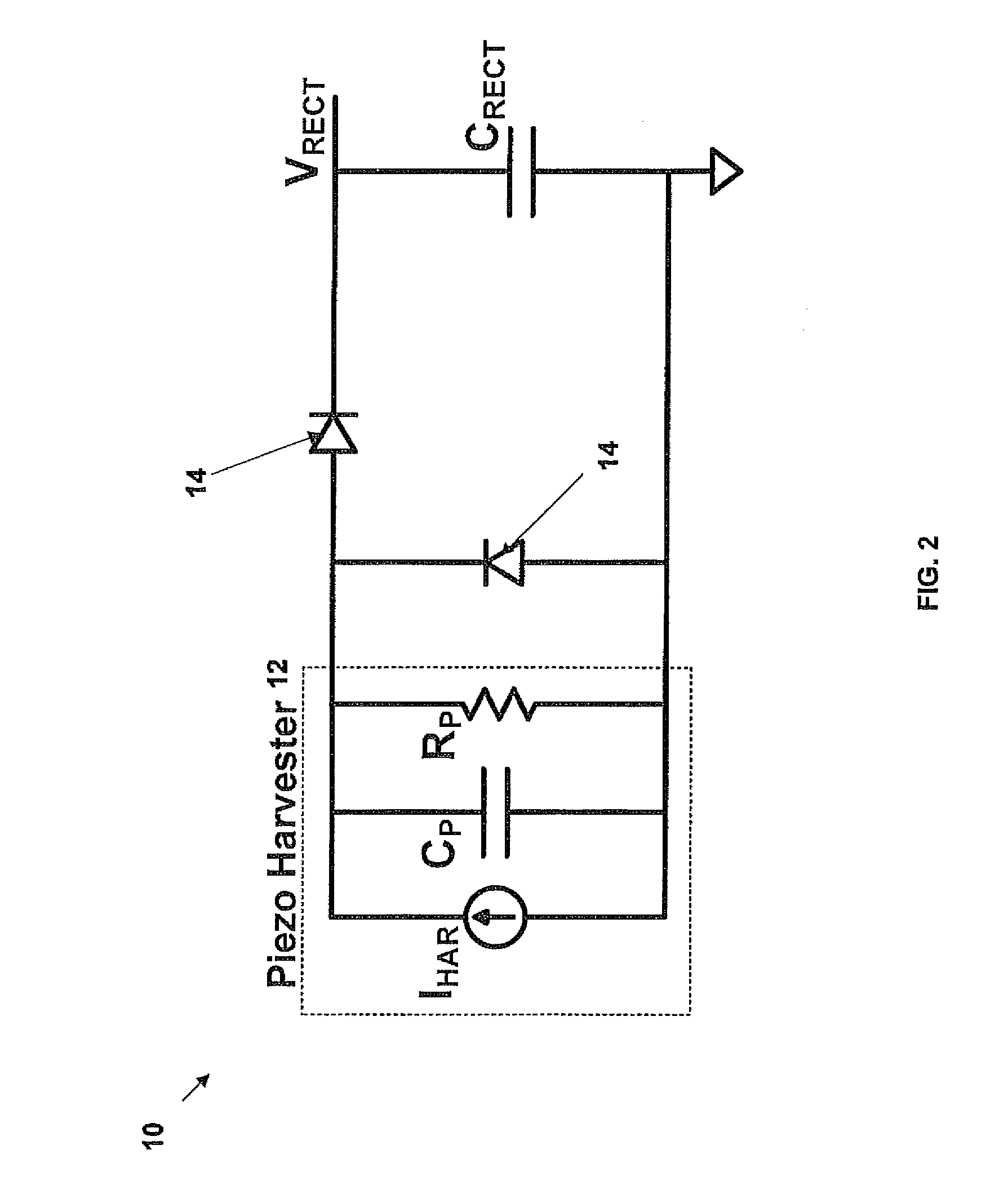
The problem with a simple full-bridge strategy is that most of the available power of the harvester 4 is just wasted in charging and discharging the input capacitor.
The main limitation of the full-bridge rectifier 2 is that, most of the current available from the harvester 4 does not go into the output at high voltages.
This loss in charge due to charging and discharging of Cp limits the maximum power that can be extracted using the full-bridge rectifier.

Method used


Image

  • Circuit and method to improve energy harvesting efficiency in piezoelectric harvesters
  • Circuit and method to improve energy harvesting efficiency in piezoelectric harvesters
  • Circuit and method to improve energy harvesting efficiency in piezoelectric harvesters

Examples


Embodiment Construction

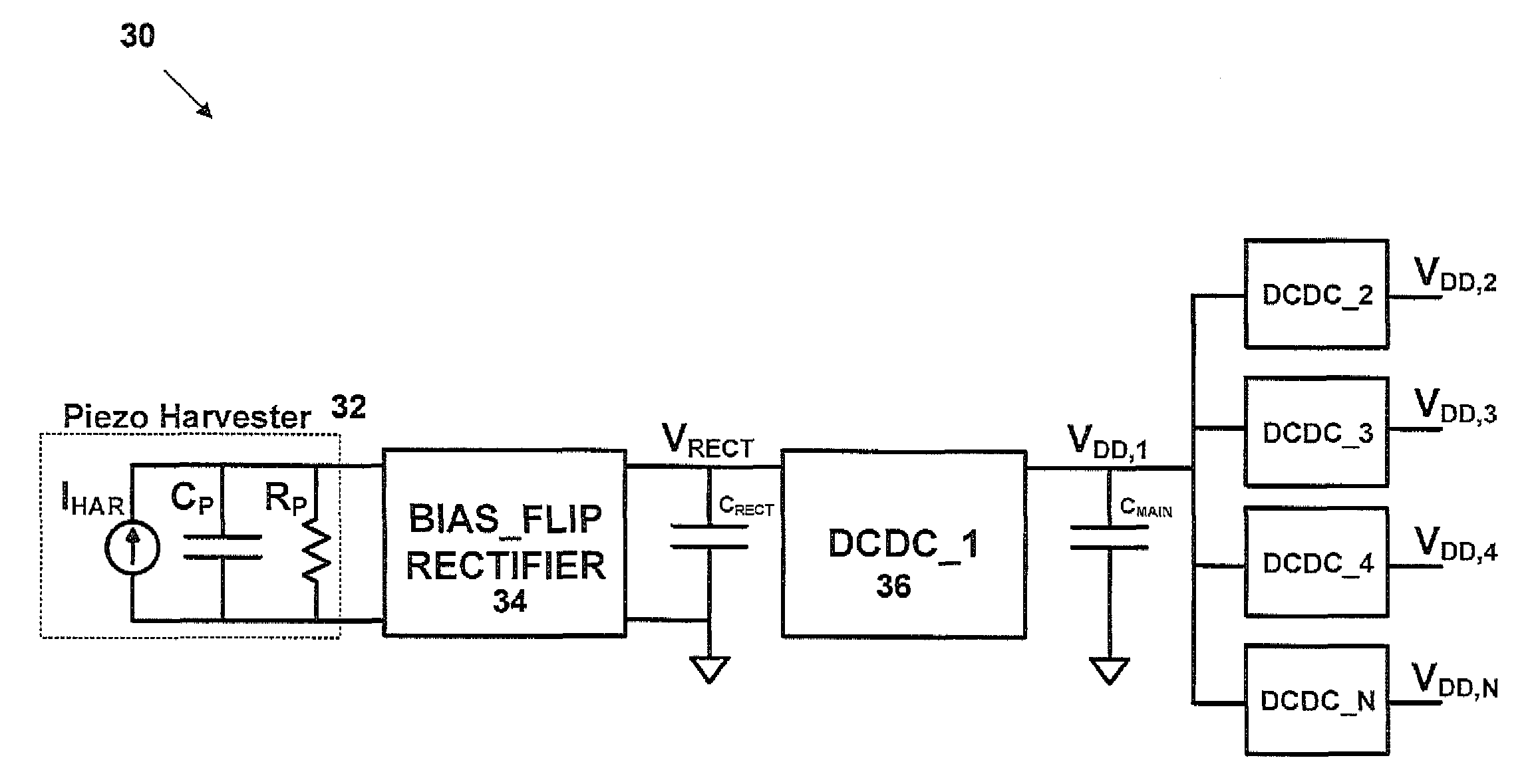
[0023]The invention provides a circuit technique to improve the energy harvesting efficiency of piezoelectric harvesters. The circuit uses a bias-flip rectifier technique which improves multi-fold, the power extraction capability as compared to conventional full-bridge rectifiers and voltage doublers. The bias-flip rectifier uses an inductor which can be shared with a multiplicity of DC-DC converters on the same energy processing circuit through an arbiter which controls access to the inductor. The circuit can be used in energy harvesting scenarios as a battery life-time enhancer or to completely eliminate the battery altogether. The invention is not limited to piezoelectric harvesters and can be used in general with any input having similar electrical characteristics to a piezoelectric harvester.

[0024]FIG. 3 shows a schematic of an exemplary embodiment of the bias-flip rectifier circuit 20 in accordance with the invention. The circuit 20 includes a regular full-bridge rectifier, ha...


PUM


Abstract

An energy harvester circuit is provided. The energy harvester circuit includes a harvesting module for extracting energy from an ambient source. A bias flip module manages the manner in which voltage across the harvesting module transitions when input current from the harvesting module changes direction so as to allow a majority of the charge available from the harvesting module to be extracted. A voltage transitioning module is shared amongst one or more DC-DC converters for efficient energy management.

Description

PRIORITY INFORMATION[0001]This application claims priority from provisional application Ser. No. 61 / 098,873 filed Sep. 22, 2008, which is incorporated herein by reference in its entirety.SPONSORSHIP INFORMATION[0002]This invention was made with governmental support under Grant Number W15P7T-08-C-P408, awarded by the US Air Force. The government has certain rights in the invention.BACKGROUND OF THE INVENTION[0003]The invention is related to the field of energy harvesting, and in particular to improving energy harvesting efficiency of piezoelectric harvesters.[0004]Energy harvesting is an area of growing importance to reduce the dependence of handheld, portable and implantable electronics on batteries. Harvesting ambient vibration energy through piezoelectric means is a popular energy harvesting technique which can supply 100's of μW of available power. A piezoelectric element converts mechanical energy in the form of vibrations into electrical energy and vice-versa. It can be modeled...

Claims


Application Information

Patent Timeline
Patent Type & Authority Patents(United States)
IPC IPC(8): H01L41/113
CPCH02N2/123H02N2/181
Inventor RAMADASS, YOGESHCHNADRAKASAN, ANANTHA
Owner MASSACHUSETTS INST OF TECH
Why Eureka
Eureka Blog
Learn More