Pressure sensor and method for manufacturing the same

a technology of pressure sensor and manufacturing method, which is applied in the direction of fluid pressure measurement, fluid pressure measurement by electric/magnetic elements, instruments, etc., can solve the problems of enlarging the outside diameter of the case, affecting the electrical connection between the sensor chip and the terminal, and affecting the accuracy of the measurement results. , to achieve the effect of reducing the size of the pressure sensor, and reducing the width of the sensor chip in the vertical

Inactive Publication Date: 2011-10-04
DENSO CORP
View PDF32 Cites 13 Cited by
  • Summary
  • Abstract
  • Description
  • Claims
  • Application Information

AI Technical Summary

Benefits of technology

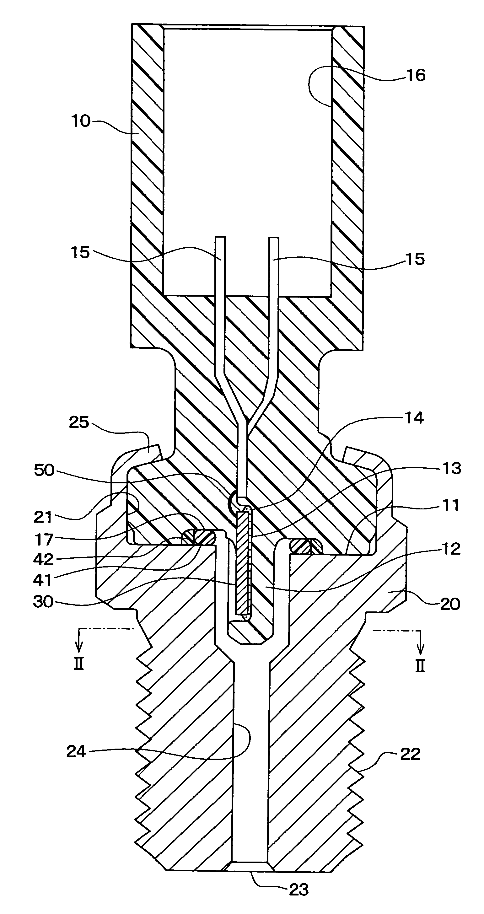
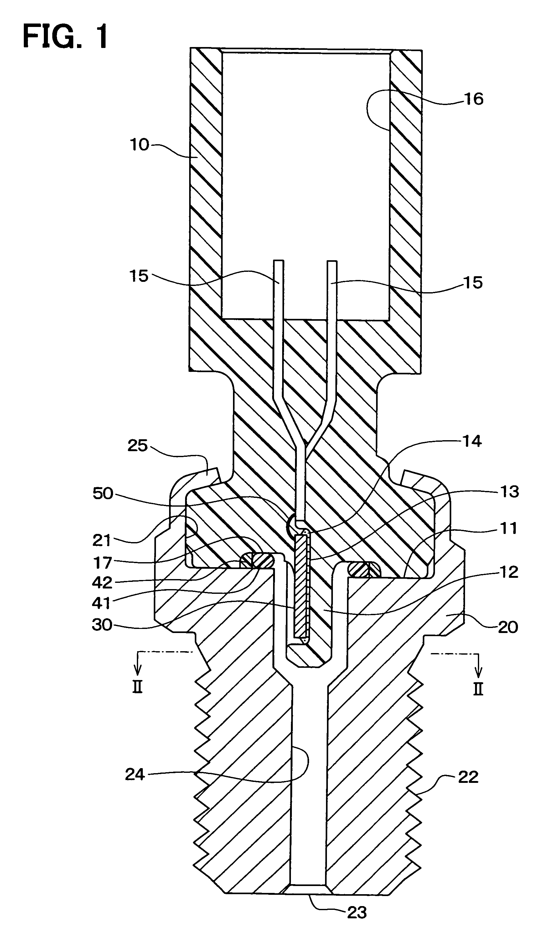
[0021]According to this, the width of the sensor chip in a direction vertical to the introduction direction of the pressure medium can be reduced by the arrangement of the sensor chip. With this, the size in a radial direction of the pressure sensor can be reduced and by extension the size of the pressure sensor can be reduced.
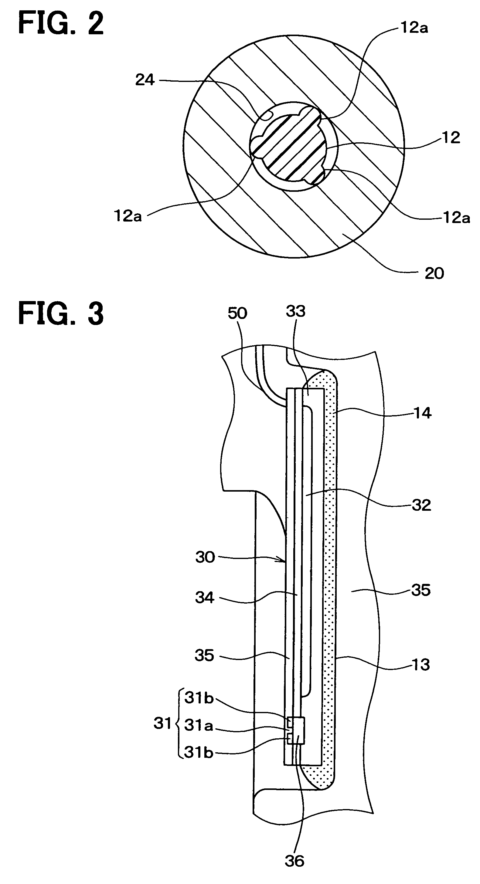
[0031]In the above sensor, thermal stress transmitted to the sensor chip from the terminal is transmitted only to a portion, which is close to the bottom side of the groove portion, of the one plane of the sensor chip. Moreover, the gate part is located at a portion, which is close to the opening side of the housing, of the one plane of the sensor chip, so that if the thermal stress does not cross the sensor chip in one direction from the bottom side of the groove portion to the opening side, the thermal stress does not reach the gage part. Thus, it is possible to make it harder for the thermal stress to be transmitted to the gage part and hence to reduce the effect of the thermal stress exerted on the gage part. With this, it is possible to increase the accuracy of detecting pressure.

Problems solved by technology

However, in the related art, the pressure receiving plane of the sensor chip is arranged vertically to the direction in which the pressure medium is introduced and hence the bonding wire needs to be extended on the same plane as the pressure receiving plane from the pressure receiving plane of the sensor chip, which results in enlarging the outside diameter of the case.
In this manner, the related art presents a problem that the outside diameter of the pressure sensor results in being enlarged.
That is, there is presented a problem that the bonding wire is broken by the pulsation of the pressure medium, which results in interrupting the electric connection of the sensor chip and the terminal.
However, the related art described above presents the following problem: that is, when the pressure sensor receives ambient temperature and the temperature of a pressure medium, because the case made of resin, the bump made of metal, and the sensor chip made of semiconductor are different from each other in the coefficient of linear expansion, a thermal stress is caused by the expansion of the case made of resin having the largest coefficient of linear expansion and is transmitted to the sensor chip made of semiconductor having the smallest coefficient of linear expansion via the wiring board and the bumps.
This reduces the accuracy of detecting the pressure.

Method used


Image

  • Pressure sensor and method for manufacturing the same
  • Pressure sensor and method for manufacturing the same
  • Pressure sensor and method for manufacturing the same

Examples


second embodiment

[0117]In this embodiment, only parts different from those in the first embodiment will be described. In the first embodiment, the connector case 10 and the housing 20 are sealed by the O ring 41 or the like, but this embodiment is characterized by employing a gasket.

[0118]FIG. 4 is a schematic sectional view of a pressure sensor according to a second embodiment of the present disclosure. As shown in this drawing, the groove 17 shown in FIG. 1 is not formed on the tip plane 11 of the connector case 10 but the tip plane 11 is formed in an end plane. Moreover, a metal gasket 43 is arranged on the other end side of the housing 20, that is, between the end on the receiving and depressed portion 13 side of the housing 20 and the connector 10.

[0119]The one end portion of the connector case 10 is inserted into a receiving and depressed portion 21 of the housing 20, and the end portion of the housing 20 is crimped on the one end portion of the connector 10 to form the crimp portion 25. With ...

third embodiment

[0121]In this embodiment, only parts different from those in the second embodiment will be described. FIG. 5 is a schematic sectional view of a pressure sensor according to a third embodiment of the present disclosure. As shown in this drawing, a tapered plane 26 is formed on the opening portion on the other end side of the housing 20 of the pressure introduction port 24 formed in the housing 20.

[0122]According to this, when the one end portion of the connector 10 is inserted into the depressed portion 13 as the receiving and depressed portion of the housing 30, the protruding portion 12 protruding from the tip plane 11 of the connector case 10 can be inserted into the pressure introduction port 24 while sliding on the tapered plane 26. Thus, the connector case 10 can be easily mounted in the housing 20.

[0123]The tapered plane 26 of the housing 20 can be also employed for the housing 20 according to the first embodiment.

fourth embodiment

[0124]In this embodiment, only parts different from those in the first embodiment will be described. FIG. 6 is a schematic sectional view of a pressure sensor according to a fourth embodiment of the present disclosure. As shown in this drawing, the groove 17 shown in FIG. 1 is not formed on the tip plane 11 of the connector case 10 but the tip plane 11 is formed in a flat plane. Moreover, the protruding portion 12 protruding from the tip plane 11 of the connector case 10 has the backup ring 42 and the O ring 41 arranged thereon in this order from the tip plane 11 side. In other words, the backup ring 42 and the O ring 41 are arranged between the side surface of the protruding portion 12 and the wall surface of the pressure introduction port 24.

[0125]According to this, the backup ring 42 and the O ring 41 can seal a shaft and hence the size of the pressure sensor can be further reduced. Moreover, since the backup ring 42 and the O ring 41 are arranged in the introduction direction of...


PUM


Abstract

A pressure sensor includes: a housing having a pressure introduction port; and a connector case integrated with the housing. The connector case includes: a protruding portion that protrudes in the pressure introduction port along with the introduction direction from one end of the connector case, and has a concavity hollowed in a direction perpendicular to the introduction direction; a sensor chip having a pressure gauge on one surface of the chip in the concavity; a terminal having one end inserted and molded in the connector case; and a bonding wire that electrically connects the sensor chip and the one end of the terminal. The connector case seals a connection portion between the bonding wire and the terminal, a connection portion between the boding wire and the sensor chip, and the bonding wire.

Description

CROSS REFERENCE TO RELATED APPLICATIONS[0001]This application is based on Japanese Patent Applications No. 2007-213487 filed on Aug. 20, 2007, and No. 2008-63869 filed on Mar. 13, 2008, the disclosures of which are incorporated herein by reference.FIELD OF THE INVENTION[0002]The present disclosure relates to a pressure sensor and a method for manufacturing a pressure sensor.BACKGROUND OF THE INVENTION[0003]A pressure sensor in which even if a pressure medium is brought into direct contact with the pressure receiving plane of a pressure detection element or with a bonding wire connected to the pressure receiving plane, the pressure detection element is protected and an electric leak is prevented is proposed in the related art, for example, in a patent document 1.[0004]Specifically, the patent document 1 proposes the pressure sensor including: a housing into which a pressure medium is introduced; a case mounted in the housing; a sensor chip as a pressure detection element which is mou...

Claims


Application Information

Patent Timeline
Patent Type & Authority Patents(United States)
IPC IPC(8): G01L7/00
CPCG01L19/0069G01L19/0084G01L19/141G01L19/143G01L19/0092Y10T29/49002H01L24/32H01L2224/48091H01L2224/73265H01L2924/181H01L2924/351H01L2924/00014H01L2924/00
Inventor OTSUKA, KIYOSHIMAKINO, YASUAKIFUKADA, TSUYOSHITOYODA, INAOKAKOIYAMA, NAOKI
Owner DENSO CORP
Why Eureka
Try Eureka