Cryostat comprising a cryogen vessel suspended within an outer vacuum container

a cryostat and vacuum container technology, applied in the direction of magnets, non-pressure vessels, superconducting magnets/coils, etc., to achieve the effect of reducing heat influx and low thermal conductivity

Inactive Publication Date: 2011-10-04
SIEMENS PLC
View PDF2 Cites 5 Cited by
  • Summary
  • Abstract
  • Description
  • Claims
  • Application Information

AI Technical Summary

Benefits of technology

[0004]Conventionally, a number of supporting elements 7 are connected between the cryogen vessel 2 and the outer vacuum container 4 to bear the weight of the cryogen vessel. These may be tensile bands, tensile rods, straps, compression struts or any known element suitable for the purpose. The elements should have a very low thermal cond

Problems solved by technology

A disadvantage of the conventional arrangement results from the fact that the outer vacuum cont

Method used


Image

  • Cryostat comprising a cryogen vessel suspended within an outer vacuum container
  • Cryostat comprising a cryogen vessel suspended within an outer vacuum container
  • Cryostat comprising a cryogen vessel suspended within an outer vacuum container

Examples


Embodiment Construction

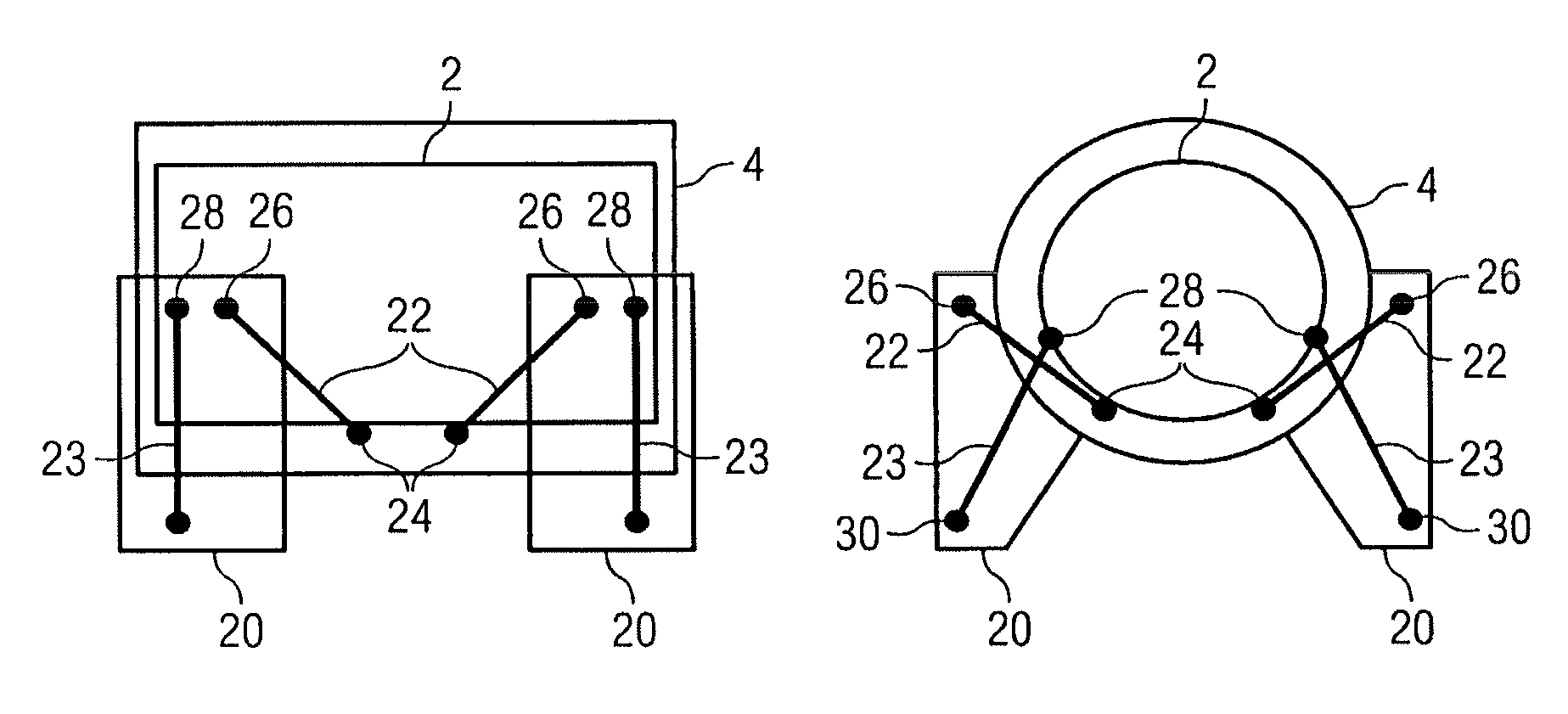
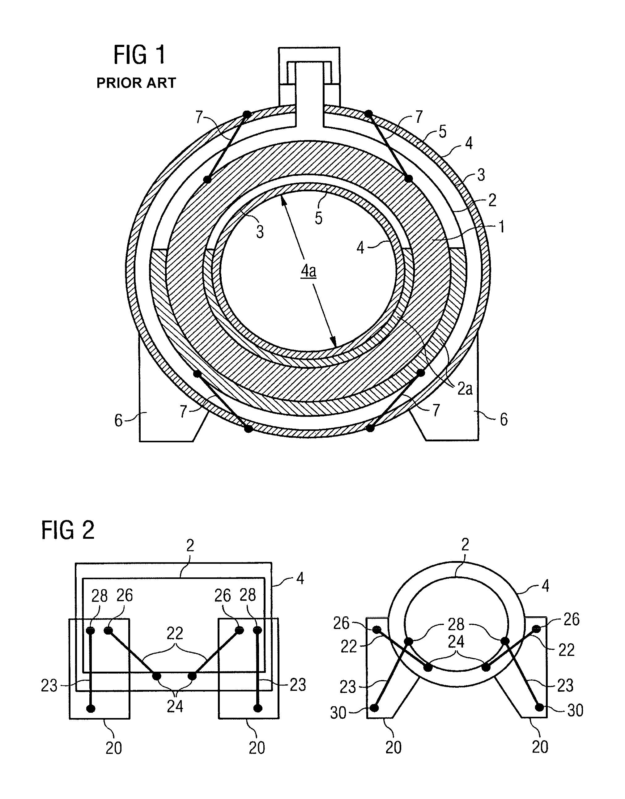
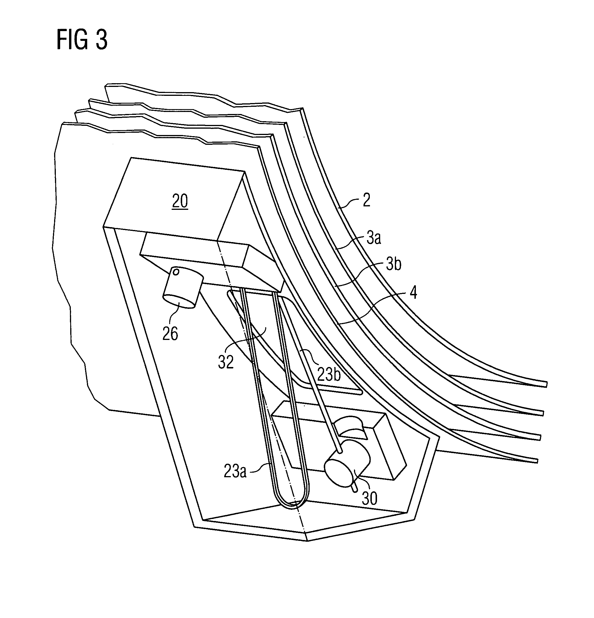
[0014]FIG. 2 schematically illustrates the principle of the present invention, wherein a housing is provided in the form of a foot 20, providing floor mounting for the system, and supporting at least some of the weight of cryogen vessel and the outer vacuum container. In some embodiments, a single housing (foot) is provided along each side of the outer vacuum container 4. In alternative embodiments, a plurality of housings (feet) may be placed at selected locations along each side of the outer vacuum container 4. The locations will be selected so as to provide an acceptable combination of floor support for the system as a whole, and support for the cryogen vessel 2 within the outer vacuum container 4.

[0015]As shown in FIG. 2, the support arrangement of the present invention typically involves a plurality of upper support elements 22 and a plurality of lower support elements 23. The upper support elements 22 connect between a relatively low point 24 on the cryogen vessel and a relati...


PUM

PropertyMeasurementUnit
Weightaaaaaaaaaa
Tensionaaaaaaaaaa

Abstract

A cryostat comprises a cryogen vessel suspended within an outer vacuum container, the cryogen vessel is supported by an arrangement that includes at least one housing mounted on an exterior surface of the outer vacuum container and arranged to function as a floor mounting foot, for supporting weight of the cryogen vessel and the outer vacuum container, and at least two mounting points mounted within the housing(s). Each of at least two suspension elements (an upper suspension element and a lower suspension element) extends through a hole in the surface of the outer vacuum container, between the respective mounting point and a respective point on the cryogen vessel.

Description

[0001]The present invention relates to arrangements for suspending an article within a vessel, and particularly relates to arrangements for suspending a cryogen vessel within an outer vacuum container. Such arrangements are useful in housing magnets for imaging systems such as magnetic resonance imaging (MRI) or nuclear magnetic resonance (NMR) systems. The present invention, however, finds application in any applications which require a cryogen vessel to be suspended within a vacuum filled outer vessel.BACKGROUND AND SUMMARY OF THE INVENTION[0002]FIG. 1 illustrates a cross-sectional view of a conventional solenoidal magnet arrangement for a nuclear magnetic resonance (NMR) or magnetic resonance imaging (MRI) system. A number of coils of superconducting wire are wound onto a former 1. The resulting assembly is housed inside a cryogen vessel 2 which is at least partly filled with a liquid cryogen 2a at its boiling point. The coils are thereby held at a temperature below their critica...

Claims


Application Information

Patent Timeline
IPC IPC(8): F17C1/00
CPCF17C3/085G01R33/3804G01R33/3815Y10T29/49826F17C2201/035F17C2201/054F17C2203/015F17C2203/016F17C2203/0308F17C2203/0391F17C2203/0631F17C2203/0646F17C2203/0648F17C2205/018F17C2209/232F17C2221/01F17C2221/017F17C2223/0161F17C2223/033F17C2260/012F17C2270/0527F17C2270/0536Y10T428/13F17C2201/0104F17C2203/0687F17C13/007F17C13/087G01N24/08H10N60/81
Inventor HOBBS, MATTHEWMANN, NICHOLAS
Owner SIEMENS PLC
Why Eureka
Try Eureka