Ultrasonic imaging system and imaging method

a technology of ultrasonic imaging and imaging method, which is applied in the field of ultrasonic imaging system, can solve the problems of not being able to accurately identify the location of each of the temperature data, and failing to disclose anything about the temperature information of the blood,

Active Publication Date: 2011-10-04
TERUMO KK
View PDF28 Cites 9 Cited by
  • Summary
  • Abstract
  • Description
  • Claims
  • Application Information

AI Technical Summary

Problems solved by technology

However, it fails to disclose anything about how the temperature information of the blood that is measured by the temperature sensor is used, and about how the temperature information is visually presented.
Furthermore, the above two conventional devices suffer the following disadvantages: An intravascular ultrasonic device will be described by way of example.
Therefore it cannot accurately identify where each of the temperature data is measured in the blood vessel or where there is the plaque because the location where the temperature is measured cannot be specified.

Method used


Image

  • Ultrasonic imaging system and imaging method
  • Ultrasonic imaging system and imaging method
  • Ultrasonic imaging system and imaging method

Examples


first embodiment

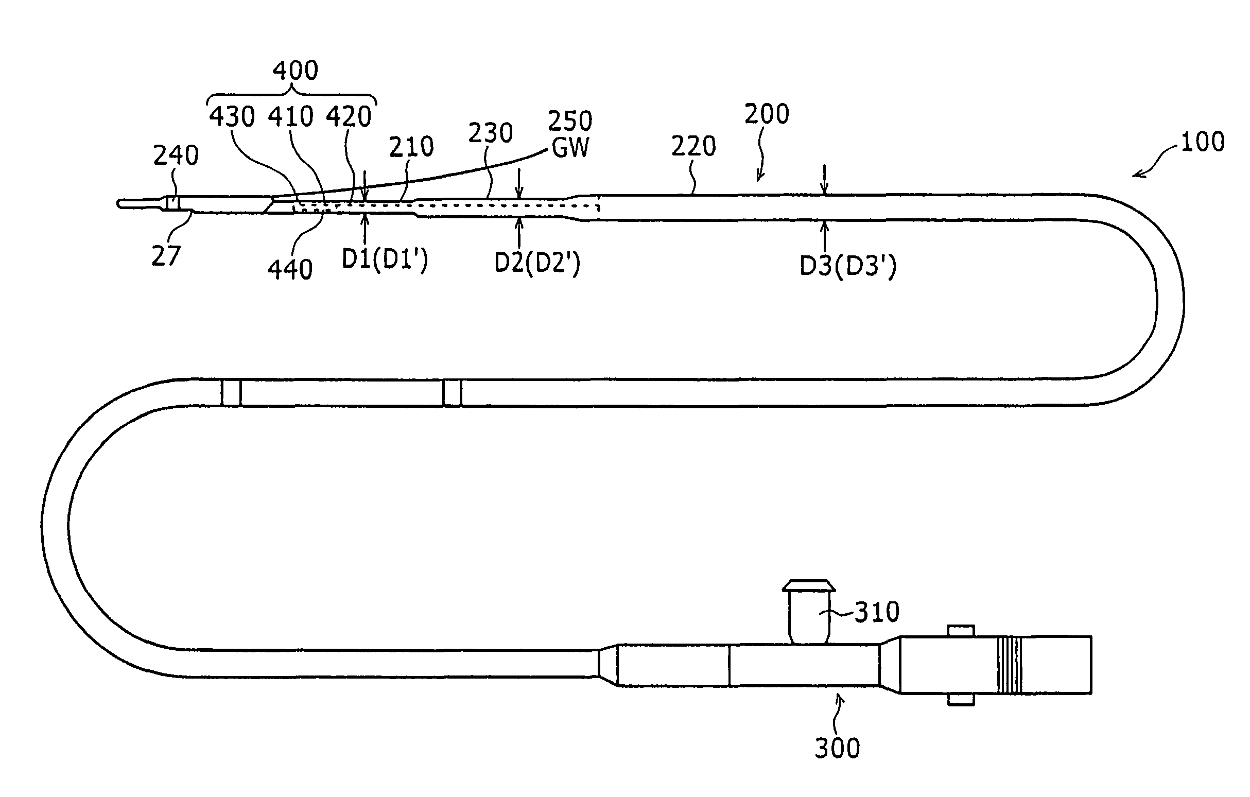
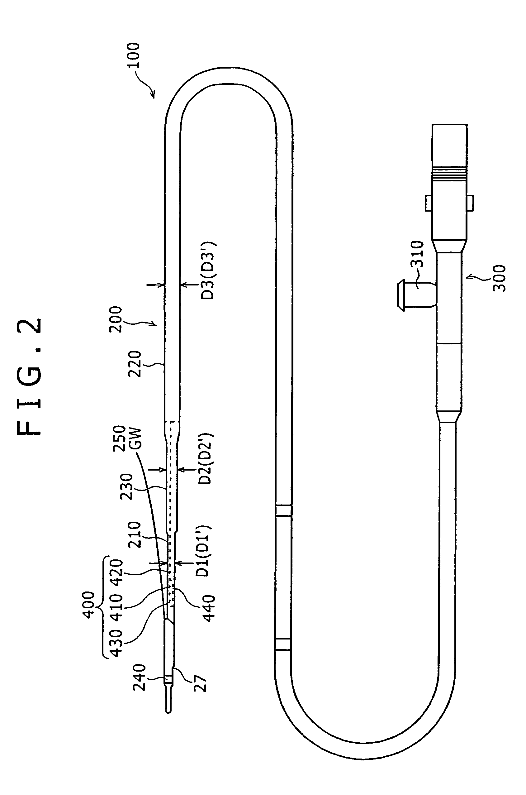
[0042]As shown in FIG. 2, the ultrasonic catheter 100 includes a sheath 200 serving as an insert to be inserted into a blood vessel and a hub 300 to be manually handled by the user. The hub 300 is positioned at a proximal end of the sheath 200 and not inserted into the blood vessel.

[0043]The sheath 200 has a sheath distal end portion 210 (see FIG. 3), a tubular sheath body 220, and an intermediate sheath portion 230. The sheath distal end portion 210 and the sheath body 220 are interconnected by the intermediate sheath portion 230. The sheath body 220 is connected to the hub 300.

[0044]The sheath distal end portion 210 has an X-ray marker 240 for giving a visual indication as to the location of the ultrasonic catheter 100 in the living body in an X-ray radioscopic image when the ultrasonic catheter 100 inserted into a blood vessel. The sheath distal end portion 210 also has a guide wire lumen for the passage of a guide wire (GW) 250 therethrough. The guide wire 250 is inserted in the...

second embodiment

[0068]FIG. 9 shows in cross section a sheath distal end portion 210 of an ultrasonic catheter according to a second embodiment of the present invention.

[0069]The sheath distal end portion 210 shown in FIG. 9 differs from the sheath distal end portion 210 according to the first embodiment shown in FIG. 3 in that a tip end coil 710 is mounted on the housing 450 according to the second embodiment. The tip end coil 710 and the metal coil 430 allow the imaging core 400 to be stably rotated by the non-illustrated motor. Therefore, the metal coil 430 serves as an X-ray marker, prevents the ultrasonic catheter from being bent, and stabilizes the rotation of the imaging core 400.

[0070]Other structural and operational details of the ultrasonic catheter according to the second embodiment, and its process of displaying an ultrasonic transverse tomographic image, an ultrasonic longitudinal tomographic image, and a temperature distribution are identical to those of the ultrasonic catheter accordi...


PUM


Abstract

An ultrasonic imaging system includes an imaging catheter and an imaging apparatus. The imaging catheter has an insert for being inserted into a blood vessel, a transducer disposed in the insert, and at least one temperature sensor disposed in the insert. The temperature sensor measures the intravascular temperature in a radial direction of the blood vessel and rotates to measure an intravascular temperature distribution in a transverse cross section of the blood vessel. The diagnostic imaging apparatus has an ultrasonic signal receiver for receiving an ultrasonic signal measured by the transducer, a temperature signal receiver for receiving an intravascular temperature signal measured by the temperature sensor, and an image constructing unit for constructing an image to be displayed from a tomographic vascular image generated from the ultrasonic signal and intravascular temperature information generated from the intravascular temperature signal, in relation to positional information of the ultrasonic signal and the intravascular temperature signal.

Description

BACKGROUND OF THE INVENTION[0001]1. Field of the Invention[0002]The present invention relates to an ultrasonic imaging system. The system is comprised of an ultrasonic imaging catheter (an ultrasonic catheter) and a diagnostic imaging apparatus for employing information obtained by the catheter for diagnostic purposes, and more particularly to an ultrasonic catheter for being inserted into a blood vessel in a living body to obtain information such as an ultrasonic image. The diagnostic imaging apparatus functions to obtain an intravascular image from information obtained by an ultrasonic catheter.[0003]2. Description of the Related Art[0004]Ultrasonic diagnostic imaging apparatus for use in body cavities generally have an ultrasonic catheter for scanning a body vessel such as a blood vessel or a vessel.[0005]FIG. 1 of the accompanying drawings shows a structure of a distal end portion 1 of such a general ultrasonic catheter. As shown in FIG. 1, the ultrasonic catheter has a catheter...

Claims


Application Information

Patent Timeline
Patent Type & Authority Patents(United States)
IPC IPC(8): A61B8/14A61B5/00A61B5/01A61B8/12
CPCA61B5/015A61B8/12A61B8/4416
Inventor HORIIKE, TOYOKAZUYAGAMI, HIROYUKIHIROTA, KAZUHIRO
Owner TERUMO KK
Why Eureka
Try Eureka