
Magnetic resonance imaging system

a magnetic resonance imaging and magnetic resonance technology, applied in the field of magnetic resonance imaging system, can solve the problems of inability to improve the snr without degrading the spatial resolution of the spectroscopic, little smoothing processing, and inability to improve the snr, etc., to achieve the effect of improving the snr

Inactive Publication Date: 2011-10-04
HITACHI LTD
View PDF9 Cites 6 Cited by
  • Summary
  • Abstract
  • Description
  • Claims
  • Application Information

AI Technical Summary

Benefits of technology

[0016]An object of the present invention is to provide a spectroscopic imaging edge-preserving filter which improves the SNR without degrading the spatial resolution of the spectroscopic imaging data.
[0017]Another object of the present invention is to provide a magnetic resonance imaging system capable of conducting high spatial and spectral resolution and high SNR spectroscopic imaging by incorporating the edge-preserving filter.
[0024]According to the magnetic resonance measuring imaging system and the magnetic resonance data processing unit according to the present invention, it becomes possible to improve the SNR without degrading the spatial resolution of spectroscopic imaging data. Furthermore, an effect that the spectrum resolution is not degraded at that time is also brought about.

Problems solved by technology

In the edge-preserving filter for ordinary images, it is difficult to improve the SNR without degrading the spatial resolution for the spectroscopic imaging data.
As for one of the two problems, the signal value changes greatly in the chemical shift dimension in a voxel where the signal intensity slightly falls from the peak, whereas in the spatial dimension the SNR is low and consequently little smoothing processing is conducted, improvement of the SNR being impossible.
As for the other of the two problems, the spectrum in the chemical shift dimension becomes broad and it becomes difficult to distinguish the molecule.
In addition to the problem of handling in the chemical shift dimension, there is also a problem that detection of a dimension having a small signal intensity change is difficult because of a low spatial resolution of the spectroscopic imaging data and a small number of pixels.
If this method is applied to spectroscopic imaging, however, there is a problem that the molecular distribution difference falls.

Method used


Image

  • Magnetic resonance imaging system
  • Magnetic resonance imaging system
  • Magnetic resonance imaging system

Examples


first embodiment

[0042]Hereafter, a first embodiment of a magnetic resonance imaging system and a magnetic resonance data processing unit according to the present invention will be described.

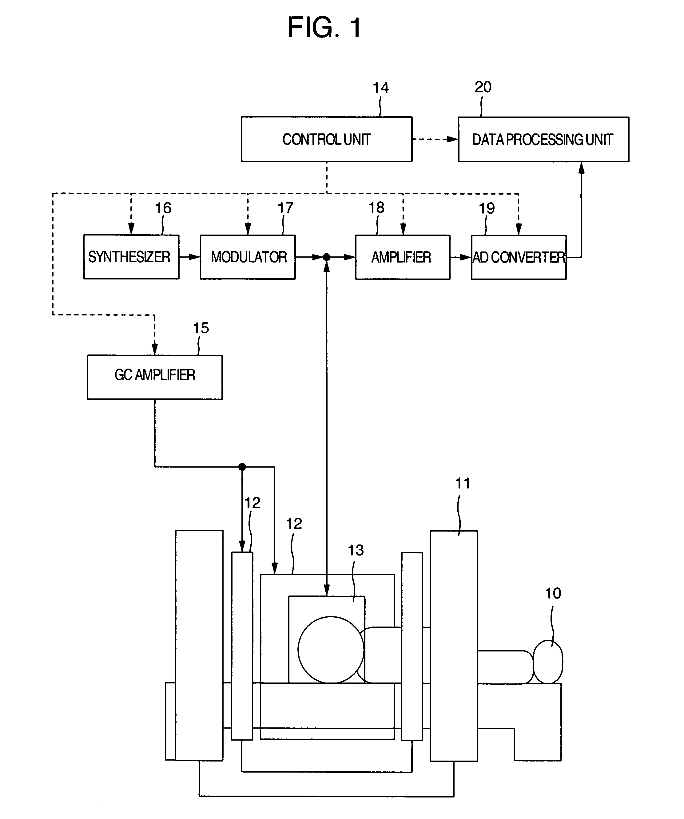
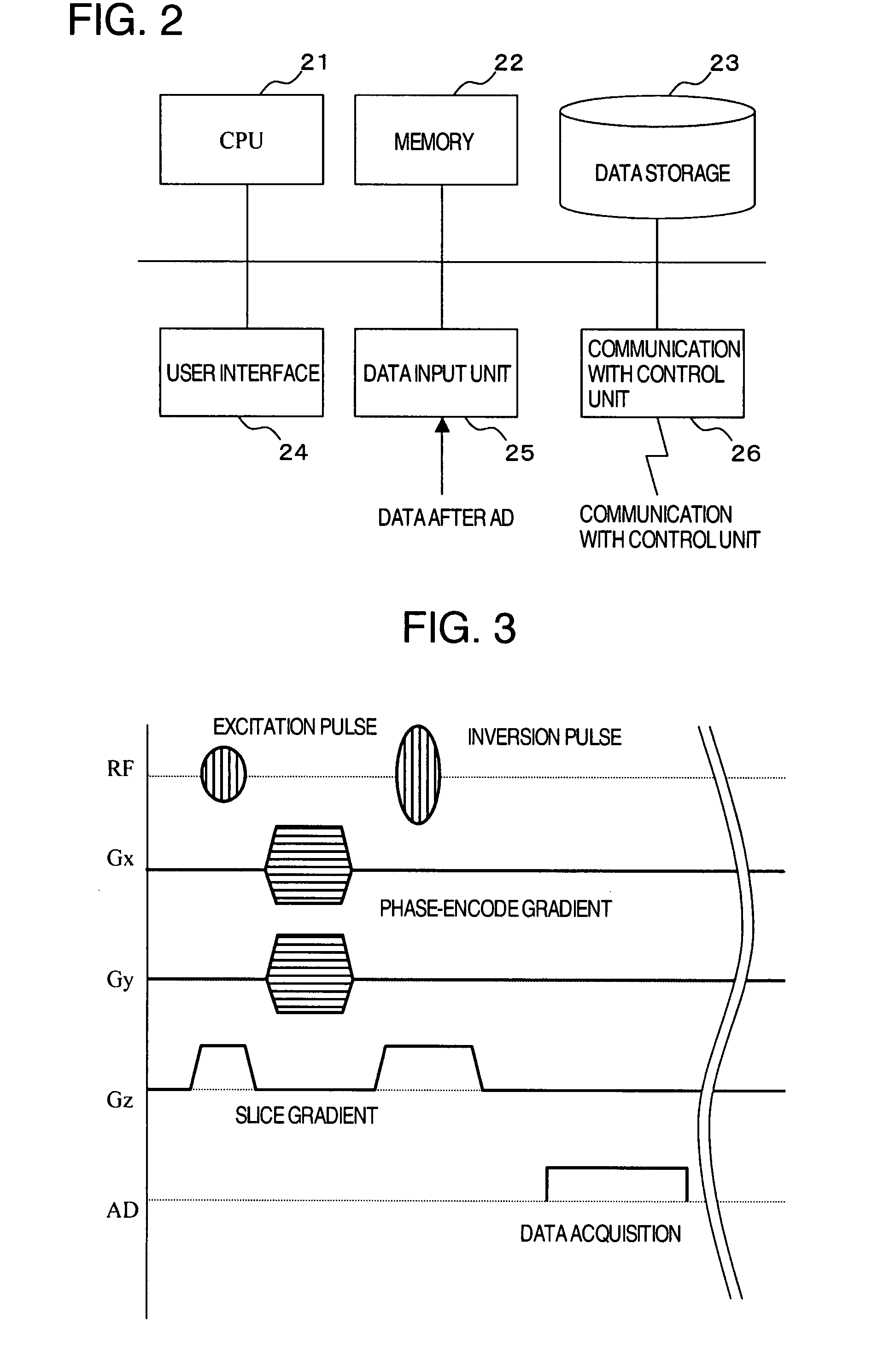
[0043]FIG. 1 is a schematic general diagram of a magnetic resonance imaging system to which the present invention is applied. The magnetic resonance imaging system mainly includes a static magnetic field generating magnet 11, gradient coils 12, an RF system 13, a control unit 14, a GC amplifier 15, a synthesizer 16, a modulator 17, an amplifier 18, an AD converter 19, and a data processing unit 20.

[0044]The synthesizer 16 and the modulator 17 form a transmission unit. An RF generated by the synthesizer 16 is subjected to waveform shaping and power amplification in the modulator 17 to supply a current to the RF system 13, thereby generate an RF field, and excite nucleus spins of a measurement object 10.

[0045]The gradient coils 12 supplied with a current from the GC amplifier 15 generate a gradient field, and modu...


PUM


Abstract

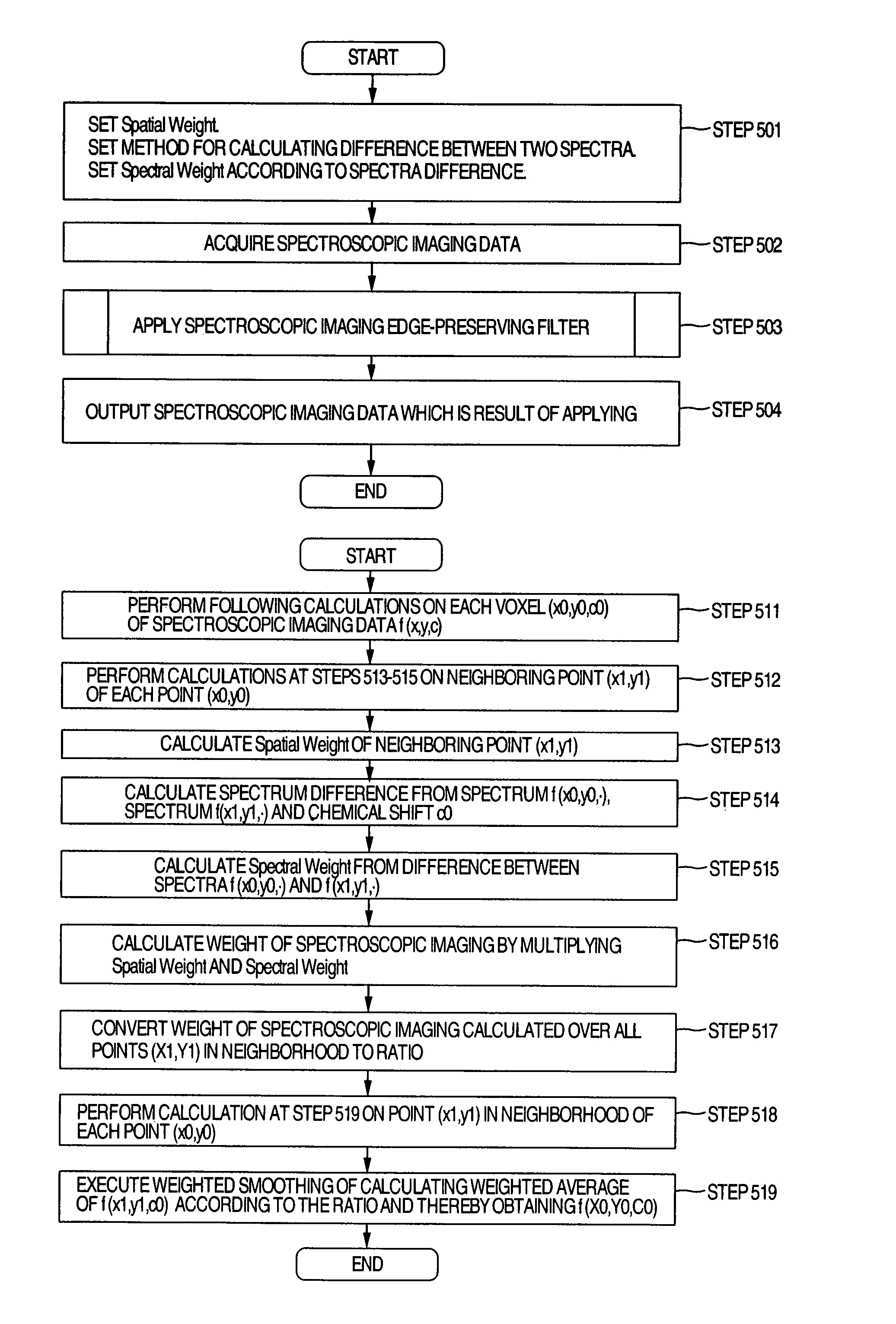
A magnetic resonance imaging system capable of conducting spectroscopic imaging with an improved SNR without degrading the spatial resolution includes edge-preserving filter processing means for spectroscopic imaging. The edge-preserving filter processing means executes processing including the steps of calculating spectral similarity in spatial neighborhoods (spatially neighboring voxels) at each voxel in spectroscopic imaging data, calculating a spectral weight according to the spectral similarity, and conducting weighted smoothing for compounding spectra of spatial neighborhoods (spatially neighboring voxels) according to the spectral weight.

Description

INCORPORATION BY REFERENCE[0001]The present application claims priority from Japanese application JP2006-132085 filed on May 11, 2006, the content of which is hereby incorporated by reference into this application.BACKGROUND OF THE INVENTION[0002]The present invention relates to a magnetic resonance imaging system (MRI system). In particular, the present invention relates to data processing of spectroscopic imaging for measuring molecular distribution.[0003]The magnetic resonance imaging system is a system which transmits a radio frequency electromagnetic field (RF) having a specific frequency to a measurement subject placed in a static magnetic field, thereby induces a magnetic resonance phenomenon, and acquires physical and chemical information of the measurement subject. Magnetic resonance imaging (MRI) that is widely spread at the present time is a method of mainly using the magnetic resonance phenomenon of the proton (1H) in the water molecule and imaging the difference in prot...

Claims


Application Information

Patent Timeline
Patent Type & Authority Patents(United States)
IPC IPC(8): G01V3/00
CPCG01R33/485G01R33/5608
Inventor BITO, YOSHITAKAOCHI, HISAAKITANIGUCHI, YOHIRATA, SATOSHISHIRAI, TORU
Owner HITACHI LTD
Learn More