Dehumidifier apparatus and method

a dehumidifier and apparatus technology, applied in the field of dehumidifiers, can solve the problems of increasing the number of electrical devices mounted in each rack, raising concerns about adequate cooling of equipment, and affecting the performance, reliability and useful life of equipment components, so as to reduce the temperature of the cooling fluid flowing and increase the temperature

Active Publication Date: 2011-10-11
AMERICA POWER CONVERSION CORP
View PDF20 Cites 12 Cited by
  • Summary
  • Abstract
  • Description
  • Claims
  • Application Information

AI Technical Summary

Benefits of technology

[0010]Embodiments of the dehumidifier unit may further include configuring the cooling fluid to flow from the source of cooling fluid with a portion of the cooling fluid flowing to the first coil and a portion of the cooling fluid flowing to the second coil and through the thermal unit. The cooling fluid may be configured to flow from one of the source of cooling fluid and the first coil to the third coil through the thermal unit. In one configuration, cooling fluid exhausted from the second coil may be configured to flow to the first coil. The thermal unit may reduce the temperature of the cooling fluid flowing to the second coil by approximately 15° F. The thermal unit may increase the temperature of the cooling fluid flowing to the third coil by approximately 25° F. A first valve may be positioned between the source of cooling fluid and the first coil with the first valve being configured to control the flow of cooling fluid to the first coil and the thermal unit. The cooling fluid exhausted from the first coil may be in fluid communication with the source of cooling fluid and the thermal unit. A second valve may be positioned between the thermal unit and the source of cooling fluid with the second valve being configured to control the flow of cooling fluid back to the source of cooling fluid.
[0014]Embodiments of the method may further include delivering cooling fluid from a source of cooling fluid to the first coil. The method may further include delivering cooling fluid from the source of cooling fluid to a thermal unit, reducing the temperature of the cooling fluid as the cooling fluid flows through the thermal unit, and delivering the reduced temperature cooling fluid from the thermal unit to a second coil. The method may also include delivering cooling fluid from one of the source of the cooling fluid and the first coil to the thermal unit, increasing the temperature of the cooling fluid as the cooling fluid flows through the thermal unit, and delivering the increased temperature cooling fluid from the thermal unit to a third coil.
[0016]Embodiments of the dehumidifier unit may further comprise a thermal unit disposed between the source of cooling fluid and the second and third coils with the thermal unit being adapted to remove heat from cooling fluid flowing to the second coil and heat cooling fluid flowing to the third coil. The cooling fluid may be adapted to flow from the source of cooling fluid with a portion of the cooling fluid flowing to the first coil and a portion of the cooling fluid flowing to the second coil through the thermal unit. Fluid flowing from one of the source of cooling fluid and the first coil may be directed to the third coil through the thermal unit. The thermal unit may reduce the temperature of the cooling fluid flowing to the second coil by approximately 15° F. The thermal unit may increase the temperature of the cooling fluid flowing to the third coil by approximately 25° F. A first valve may be positioned between the source of cooling fluid and the first coil with the first valve being configured to control the flow of cooling fluid to the first coil. A second valve may be positioned between the first coil and the source of cooling fluid with the second valve being configured to control the flow of cooling fluid to the source of cooling fluid.

Problems solved by technology

Further, with the ever decreasing size of computer equipment, and in particular, computer servers and blades, the number of electrical devices mounted in each rack has been increasing, raising concerns about adequately cooling the equipment.
Heat produced by rack-mounted equipment can have adverse effects on the performance, reliability and useful life of the equipment components.
In particular, rack-mounted equipment, housed within an enclosure, may be vulnerable to heat build-up and hot spots produced within the confines of the enclosure during operation.
A disadvantage of the CRAC-type of air conditioning system is that cool air is mixed with the room temperature air, which is inefficient.
Another disadvantage of employing CRAC-type units is that, while they are particularly suited to addressing sensible cooling, such units are not particularly suited to addressing latent cooling.
A trend emerging in the data center room cooling industry is the adoption of operating chiller plants with warmer supply set points, which increases the sensible heat ratio of conventional CRAH units and greatly reduces the moisture removal capacity of the unit.

Method used


Image

  • Dehumidifier apparatus and method
  • Dehumidifier apparatus and method
  • Dehumidifier apparatus and method

Examples


Embodiment Construction

[0024]This disclosure is not limited in its application to the details of construction and the arrangement of components set forth in the following description or illustrated in the drawings. The embodiments disclosed herein are capable of further embodiments and of being practiced or of being carried out in various ways. Also, the phraseology and terminology used herein is for the purpose of description and should not be regarded as limiting. The use of “including,”“comprising,”“having,”“containing”, “involving”, and variations thereof herein, is meant to encompass the items listed thereafter and equivalents thereof as well as additional items.

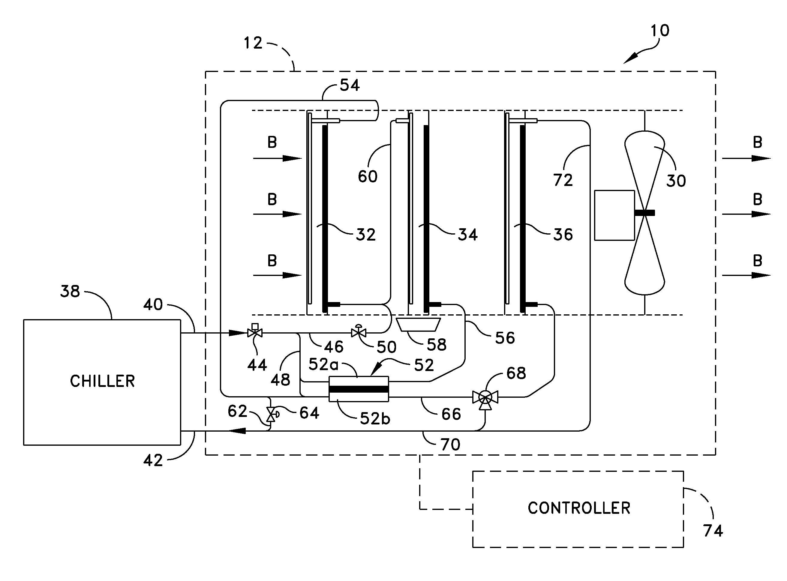
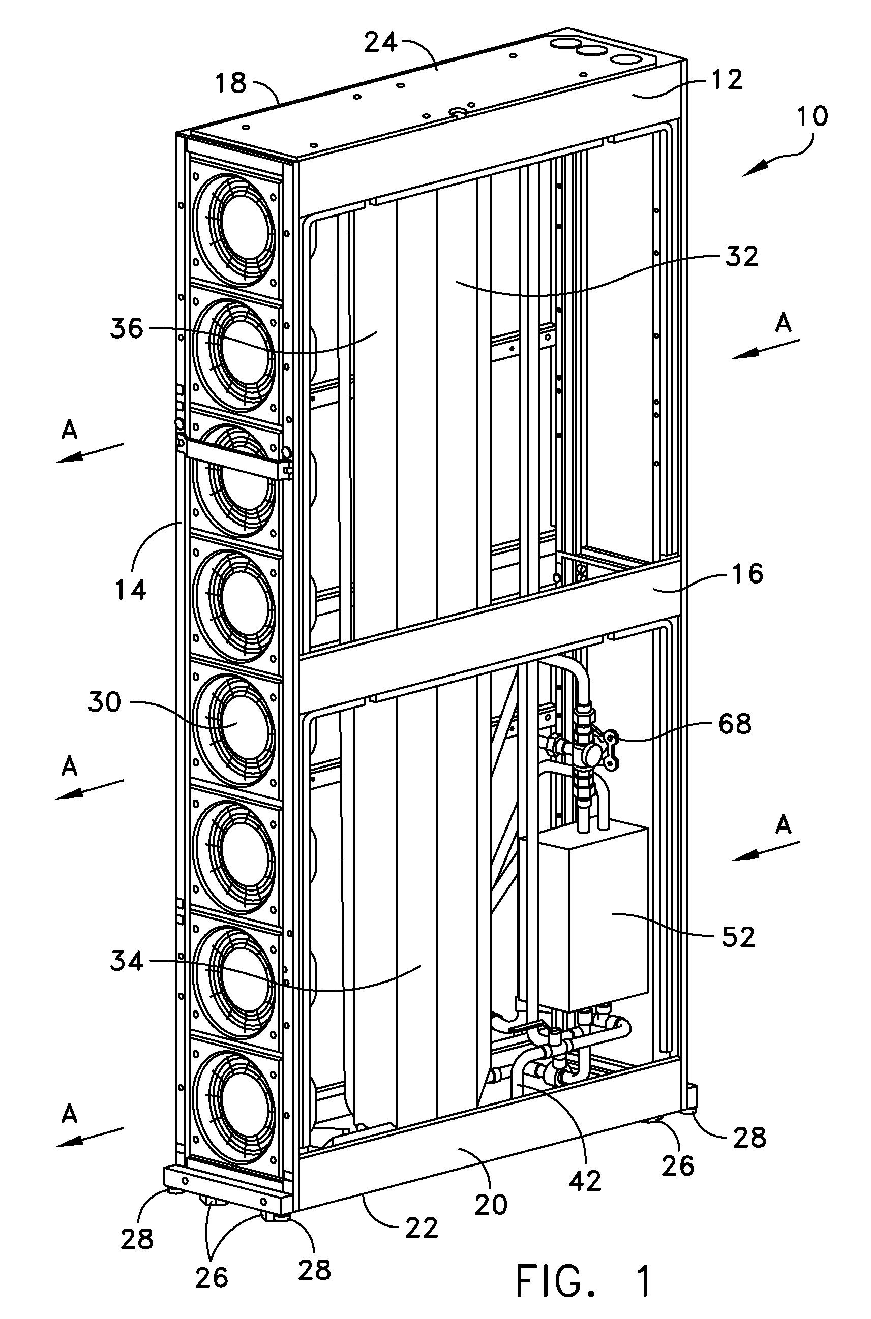
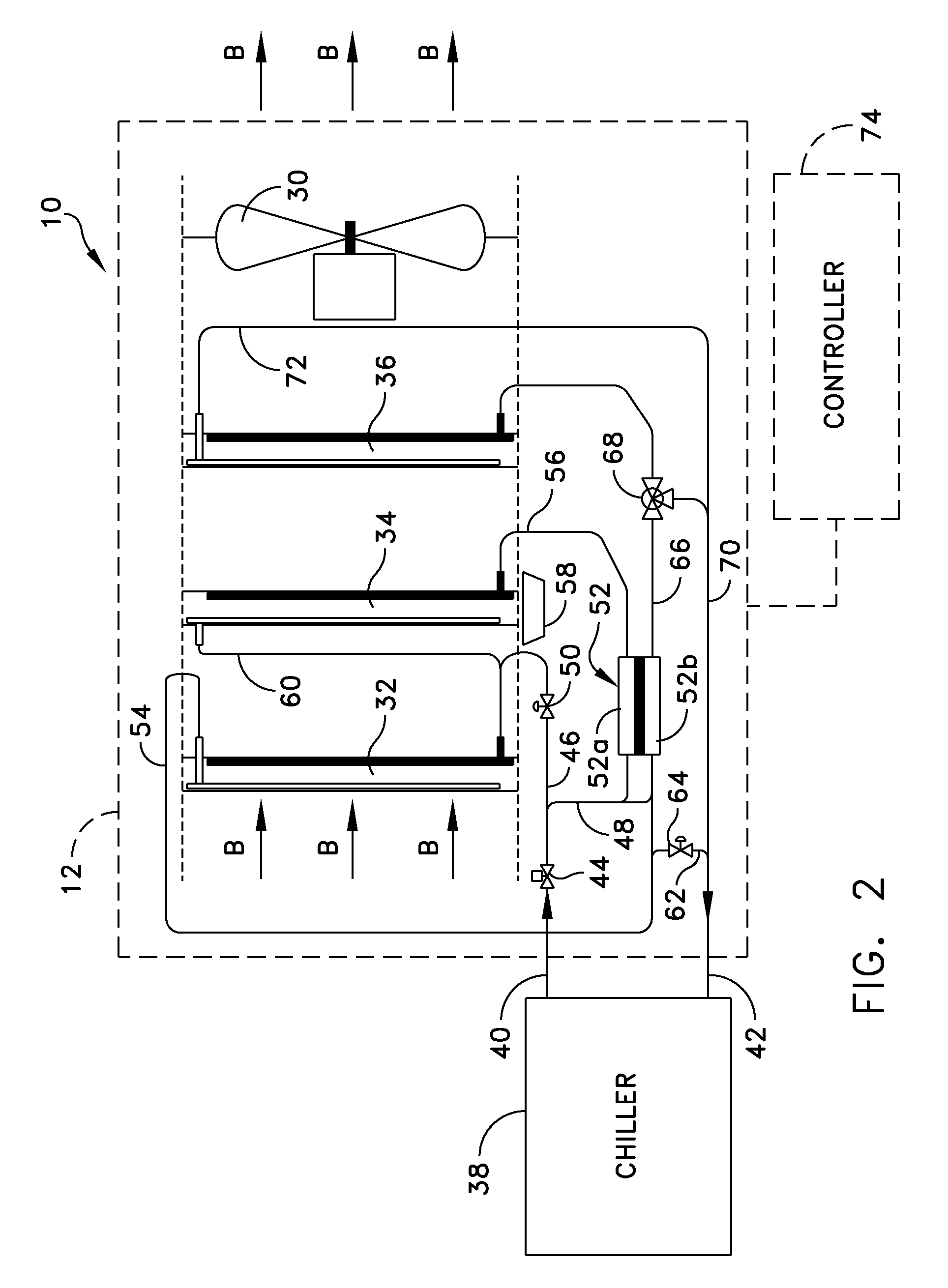
[0025]At least one embodiment of the present disclosure is directed to a modular and scalable cooling unit that is selectively configurable to cool electronic equipment housed within equipment enclosures or racks of a data center. As used herein, “enclosures” and “racks” are used to describe apparatus designed to support electronic equipment....


PUM


Abstract

A dehumidifier unit includes a first coil in fluid communication with a source of cooling fluid, a second coil in fluid communication with the source of cooling fluid, a third coil in fluid communication with the source of cooling fluid, and a thermal unit disposed between the source of cooling fluid and the second and third coils. The thermal unit may be adapted to remove heat from cooling fluid flowing to the second coil and adapted to heat cooling fluid flowing to the third coil. A fan may be configured to move air across the first, second and third coils. The first coil may be configured to pre-cool air moving over the first coil, the second coil may be configured to dehumidify the air moving over the second coil, and the third coil may be configured to warm the air moving over the third coil. Other embodiments and methods of cooling are further disclosed.

Description

BACKGROUND OF THE INVENTION[0001]1. Field of the Invention[0002]The present disclosure relates to cooling systems, and more particularly to a dehumidifying apparatus configured to be operable to condition air within a data center, and related methods for cooling or treating air within a data center.[0003]2. Discussion of Related Art[0004]Equipment enclosures or racks for housing electronic equipment, such as data processing, networking and telecommunications equipment, have been used for many years. Such racks are used to contain and to arrange the equipment in small wiring closets as well as equipment rooms and large data centers. In certain embodiments, an equipment rack can be an open configuration and can be housed within a rack enclosure, although the enclosure may be included when referring to a rack. Over the years, a number of different standards have been developed to enable equipment manufacturers to design rack mountable equipment that can be mounted in standard racks man...

Claims


Application Information

Patent Timeline
Patent Type & Authority Patents(United States)
IPC IPC(8): F25D17/06
CPCF24F3/1405H05K7/20781F24F5/0042F24F3/153
Inventor BEAN, JR., JOHN H.
Owner AMERICA POWER CONVERSION CORP
Why Eureka
Try Eureka