Centrifugal separator

a centrifugal separator and centrifugal technology, applied in the direction of centrifuges, solid separation, reversed direction vortex, etc., can solve the problems of reducing the degree of efficiency of the known centrifugal separator, the flow between the inlet channel and the fin rotor still has a relatively high twist, and the burden on the internal mill circuit is eased, so as to increase the separation sharpness

Active Publication Date: 2011-10-11
BABCOCK BORSIG STEINMUELLER GMBH
View PDF50 Cites 16 Cited by
  • Summary
  • Abstract
  • Description
  • Claims
  • Application Information

AI Technical Summary

Benefits of technology

[0014]Due to the fact that the separator pockets project into the flow path, and therefore to a certain degree block it, the twist of a part of the flow containing the coarse and fine particles is reduced, and this part of the flow is decelerated, wherein mainly coarse particles fall out of the flow due to the gravitational forces taking effect on them. These can then be conducted in a downwards movement to the grinding plate. Due to the reduction of the twist, therefore, on the one hand the separation sharpness is increased, since a separation takes place due to the effect of the gravitational forces on the coarse particles in the decelerated flow. On the other hand, at the same time the loads taking effect on the components of the separator are reduced.
[0034]According to a further embodiment of the method according to the invention, the centrifugal separator is operated at over-pressure. The centrifugal separator according to the invention can, however, as an alternative, also be operated at under-pressure. Both are possible by means of the design according to the invention of the centrifugal separator, and equally lead to a clear improvement of the separation sharpness when separating a flow containing coarse and fine particles, which in particular is a two-phase flow.

Problems solved by technology

A problem with the centrifugal separator described heretofore is that the flow between the inlet channel and the fin rotor still has a relatively high twist, and that, despite the two separator devices, a relatively large amount of coarse dust passes into the area on the other side of the fin rotor.
The consequence is a reduced degree of efficiency of the known centrifugal separator.
Despite the arrangement of such a deflector ring in the separator chamber, the coarse particles, sinking down, continue to be subjected to a twist, are conducted back into the carrier gas flow, and then impose a burden on the rotor.
Due to this, as before, a relatively high proportion of fine dust is carried along and conveyed back again, which imposes an additional burden on the internal grinding circuit.
The increased milling circuit further leads to increased pressure losses of the system as a whole, which in turn exerts a negative effect on the smooth running of such a mill and its degree of efficiency.
Moreover, the high loading of the rotor causes coarse dust to be carried out through the second outlet channel.

Method used


Image

  • Centrifugal separator
  • Centrifugal separator
  • Centrifugal separator

Examples


Embodiment Construction

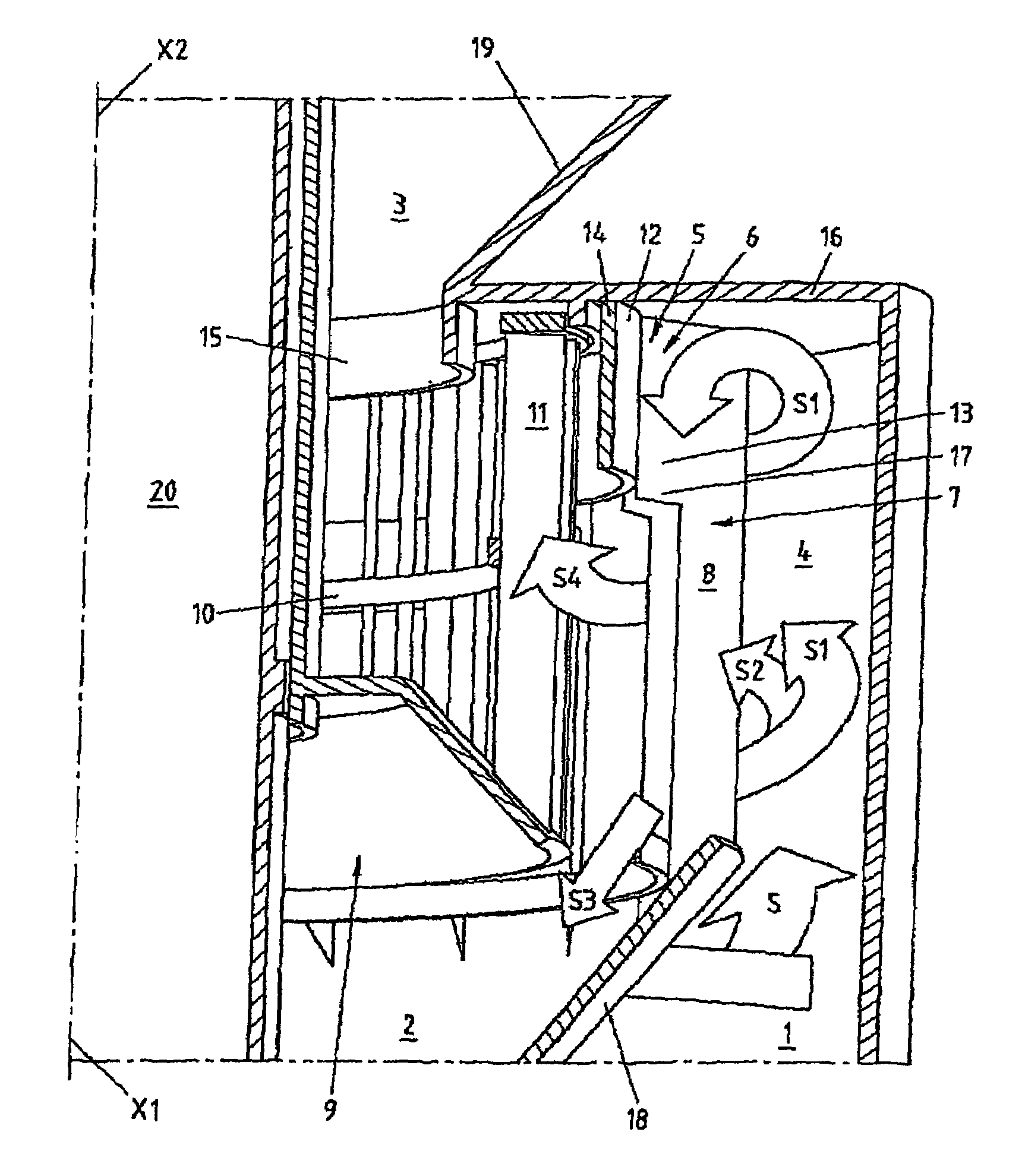
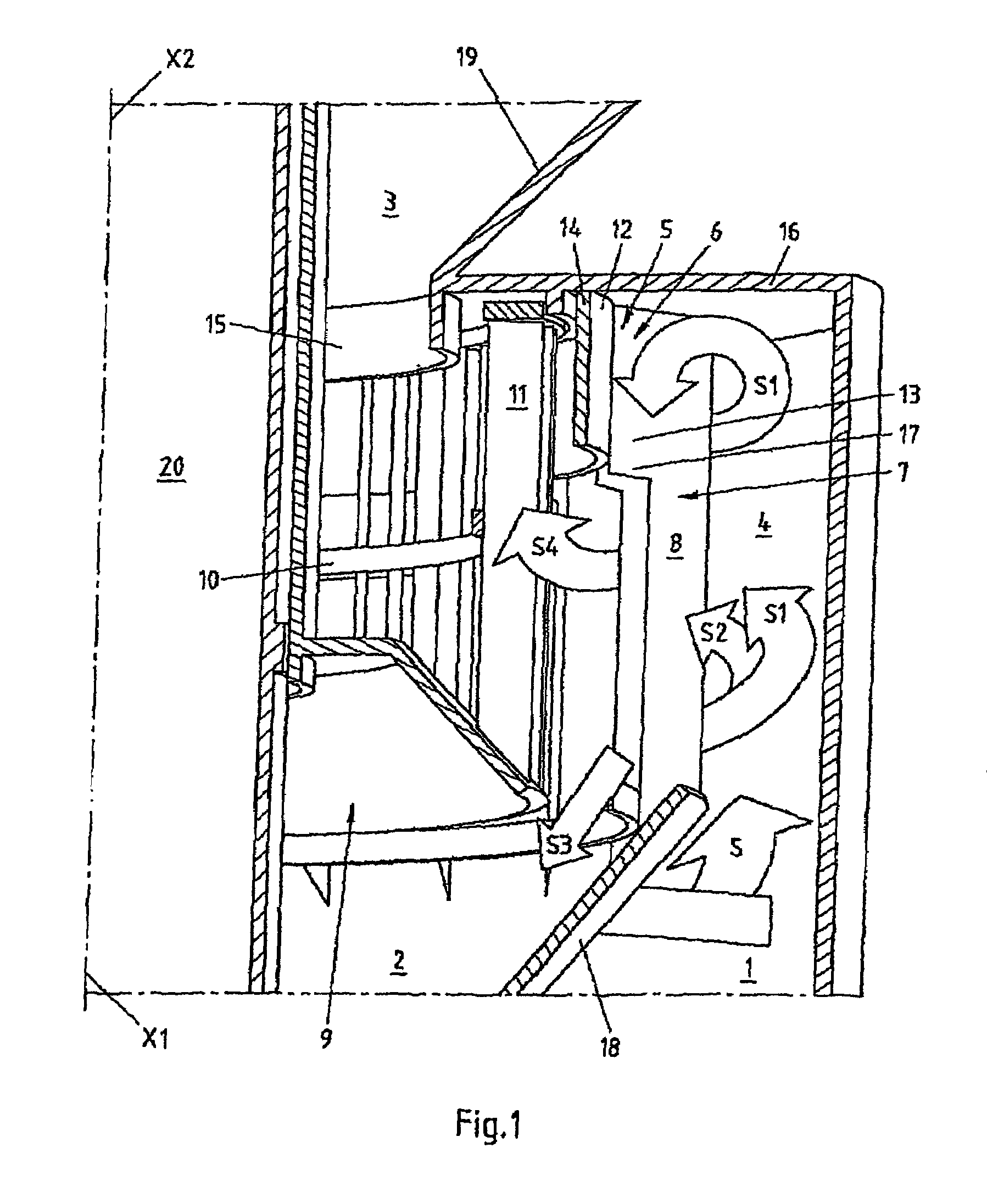
[0040]The principle representation in FIG. 1 shows a centrifugal separator in the form of a rotary separator according to an embodiment of the present invention, which has an inlet channel 1 for a two-phase flow S containing coarse and fine particles, represented here by arrows. Provision is further made for a first outlet channel 2 for a flow containing predominantly coarse particles, and a second outlet channel 3 for a flow containing predominantly fine particles.

[0041]The division into the flow containing coarse particles and the flow containing fine particles takes place in a separator chamber 4 with three separate separator devices 5, 7 and 9. The separator chamber 4 connects the inlet channel 1 with the first outlet channel 2 and the second outlet channel 3. It can further be seen that the separator chamber 4 is cylindrical in design and, as soon as the flow S which is to be separated has risen from a mill (not shown) through the intake channel 1 under the imposition of twist,...


PUM


Abstract

Disclosed is a centrifugal separator with an inlet channel for a flow containing coarse and fine particles, a first outlet channel for a flow containing predominantly coarse particles, a second outlet channel for a flow containing predominantly fine particles and a separator chamber with at least one separator device, wherein the separator chamber connects the inlet channel to the first outlet channel and the second outlet channel, and wherein the inlet channel, the separator channel and the two outlet channels form a flow path. To improve the degree of efficiency, as a first separator device, one or more separator pockets are arranged in the separator chamber, which project into the flow path. Also disclosed is a corresponding method for the separation of a flow containing coarse and fine particles.

Description

BACKGROUND OF THE INVENTION[0001]The invention relates to a centrifugal separator with an inlet channel for a flow containing coarse and fine particles, a first outlet channel for a flow containing predominantly coarse particles, a second outlet channel for a flow containing predominantly fine particles and a separator chamber with at least one separator device, wherein the separator chamber connects the inlet channel to the first outlet channel and the second outlet channel, and wherein the inlet channel, the separator chamber and the two outlet channels form a flow path.[0002]The invention further relates to a method for the separation of a flow containing coarse and fine particles with such a centrifugal separator.[0003]Centrifugal separators are devices with which coarse particles (coarse dust) are separated from fine particles (fine dust) in a flow, referred to as a two-phase flow. The particles occur, for example, in a mill for stone coal grinding by comminution of the grindin...

Claims


Application Information

Patent Timeline
Patent Type & Authority Patents(United States)
IPC IPC(8): B04B5/12
CPCB07B7/08B07B7/083
Inventor PISTORIUS, THOMASSTORM, CHRISTIAN
Owner BABCOCK BORSIG STEINMUELLER GMBH
Why Eureka
Try Eureka