

Anvil with rolling elements for friction stir welding
a technology of friction stir welding and rolling elements, applied in the field of mechanical devices, can solve the problems of large and complex anvils, difficult to present friction stir tool and anvil design, cumbersome handling, etc., and achieve the effect of reducing frictional forces and facilitating relative motion
- Summary
- Abstract
- Description
- Claims
- Application Information
AI Technical Summary
Benefits of technology
Problems solved by technology
Method used
Image

Examples
Embodiment Construction
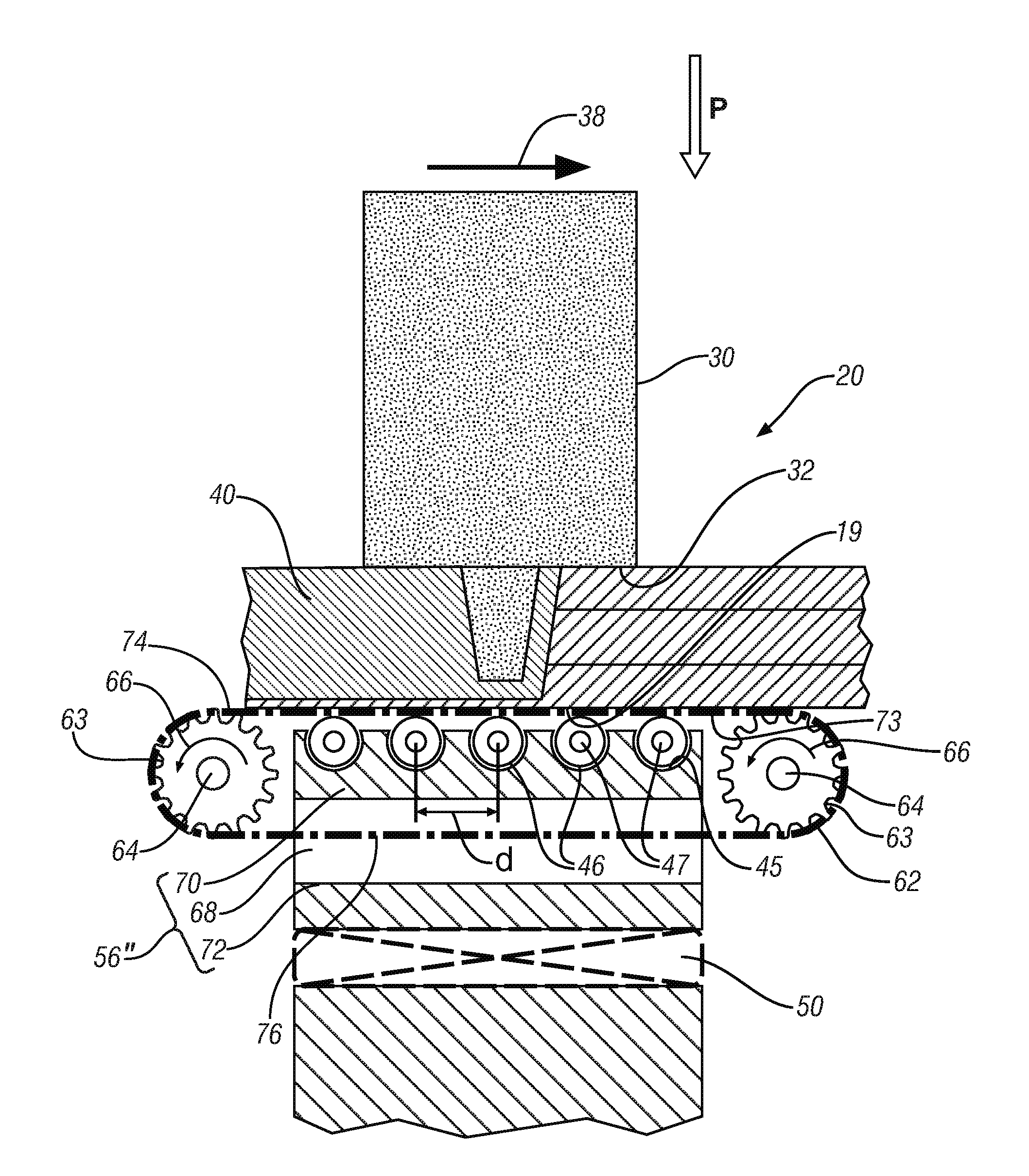
Friction stir welding is commonly practiced to form a continuous weld. The tool generally comprises a cylindrical or conical pin, although other geometries can be used, protruding from the face of a supporting second, larger, generally cylindrical feature, where the pin and the supporting member share a common centerline.
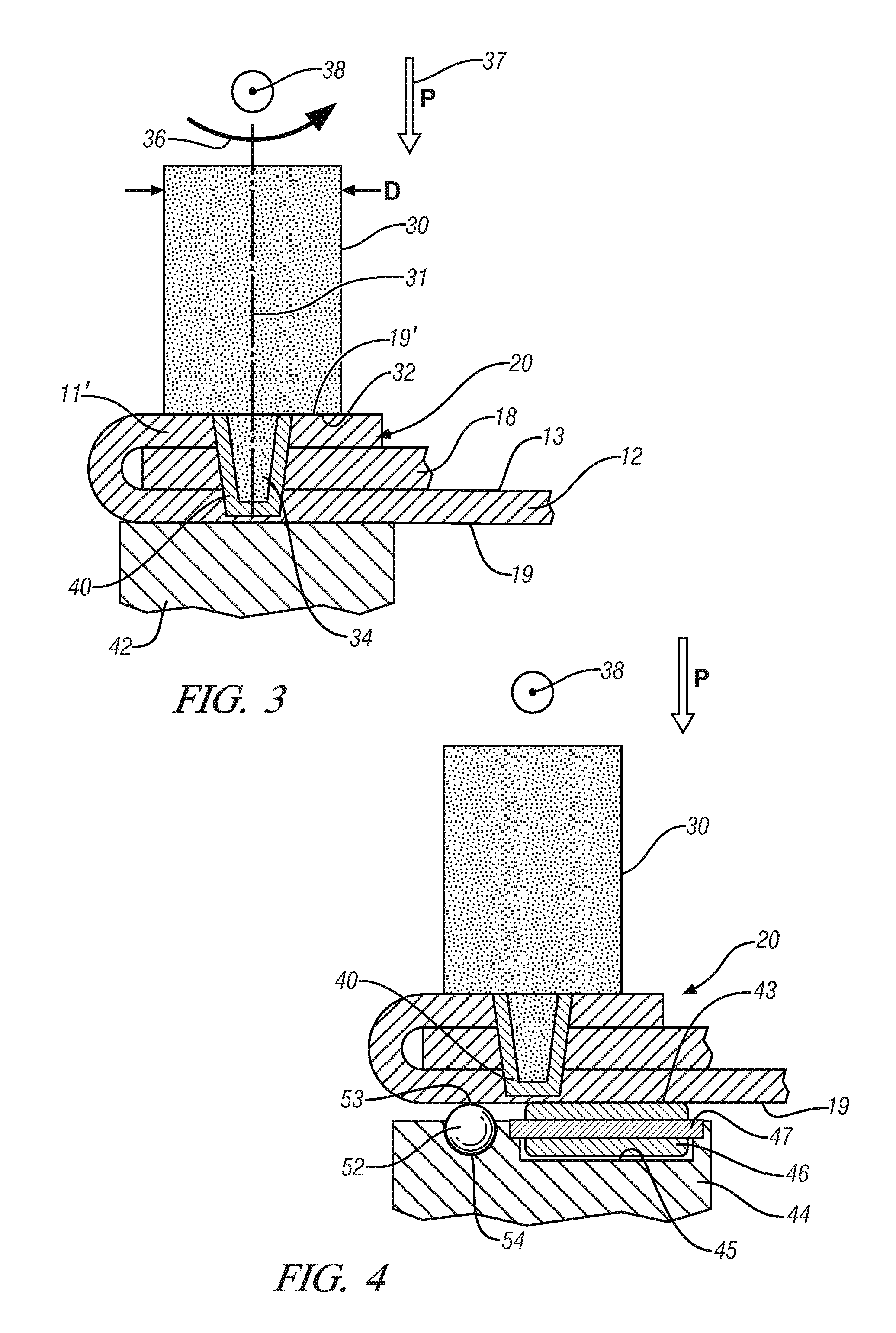
In operation, the pin is rotated about its centerline and is plunged into the workpieces to be joined until the face of the second cylindrical feature, more commonly described as the tool shoulder, just penetrates the workpiece surfaces and the pin is fully immersed in the joint. Both the shoulder and the pin generate heat through frictional interaction with the workpieces to soften and plasticize the workpieces, and the embedded rotating pin, which may incorporate features to enhance its stirring action, then stirs, kneads, mixes and commingles the workpieces. A variety of tool geometries have been developed but for the thin, less than 1 millimeter thick, sheet met...
PUM
| Property | Measurement | Unit |
|---|---|---|
| thickness | aaaaa | aaaaa |
| thickness | aaaaa | aaaaa |
| thick | aaaaa | aaaaa |
Abstract
Description
Claims
Application Information