Eureka AIR delivers breakthrough ideas for toughest innovation challenges, trusted by R&D personnel around the world.

Apparatus for manufacturing secondary battery

a secondary battery and accessory technology, applied in the manufacture of secondary cells, final product manufacturing, drawing profiling tools, etc., can solve the problems of increasing the total weight and the total size of the battery pack, low mechanical strength of the battery case b>14/b>, and not providing high sealing force, so as to achieve further improvement of structural stability

Active Publication Date: 2011-10-11
LG ENERGY SOLUTION LTD
View PDF18 Cites 2 Cited by
  • Summary
  • Abstract
  • Description
  • Claims
  • Application Information

AI Technical Summary

Benefits of technology

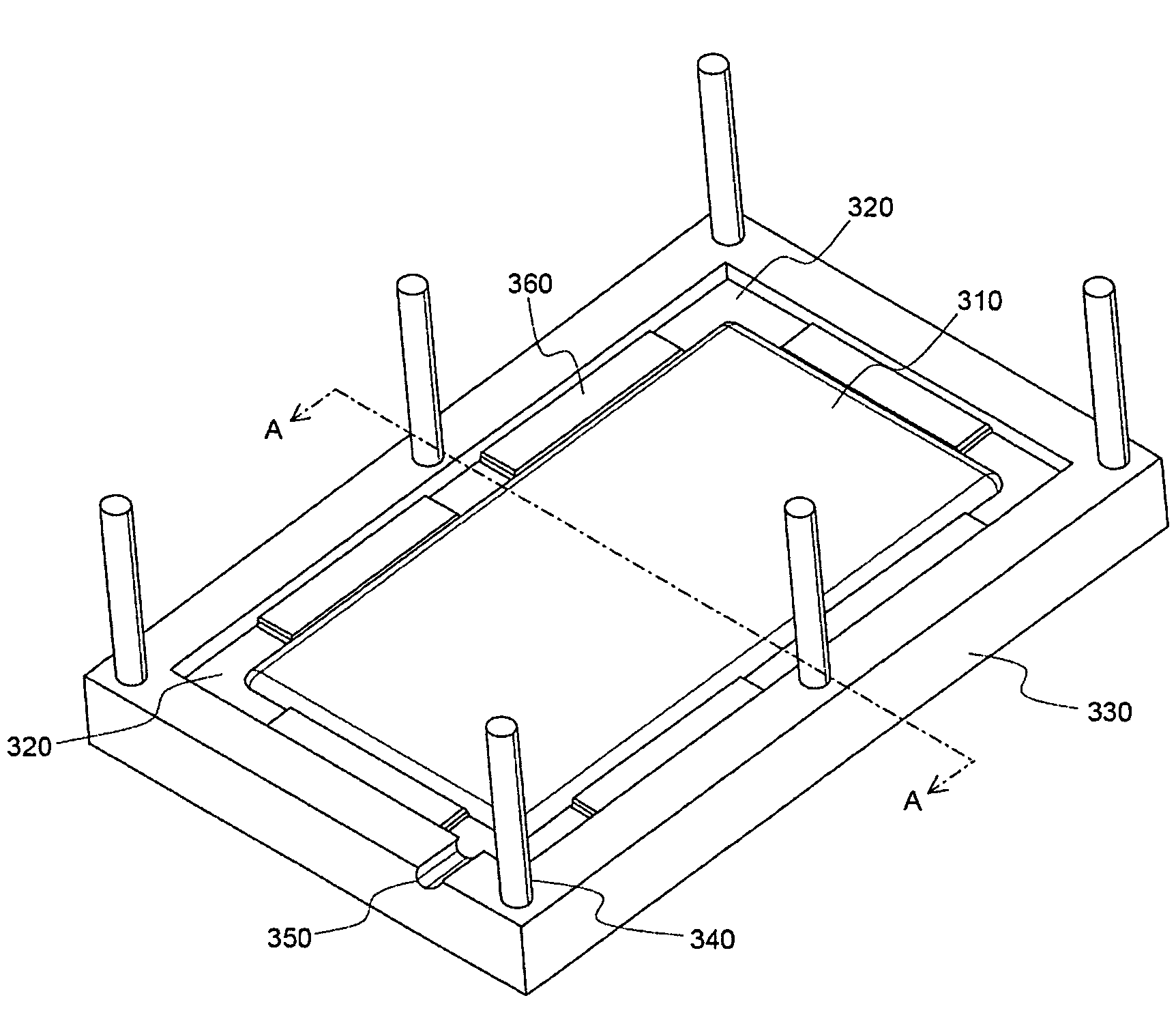
[0012]Specifically, it is an object of the present invention to provide an apparatus for manufacturing a secondary battery that is capable of preventing a battery case from being damaged when a mold is brought into tight contact with a battery cell of the secondary battery during insert injection molding to form a molding member at a specific region of the secondary battery.
[0015]In the secondary battery manufacturing apparatus according to the present invention, the cell body of the battery cell is supported by the elastic members during the insert injection molding process. Consequently, the damage to the battery case due to the direct contact between the battery case and the mold is prevented, and injection of a material for insert injection molding from a specific region where a molding member is formed (“molding region”) to other region (“non-molding region) is effectively prevented due to a high contact force of the elastic members in spite of low pressure.
[0019]As another example, the molding region formed by the insert injection molding may be an outside sealing region of the battery case. A molding part having a predetermined thickness may be formed at the sealing region by the insert injection molding. The molding part increases the mechanical strength of the battery case and the sealing force at the sealing region. Furthermore, the molding part provides structural stability when a plurality of secondary batteries are stacked one on another so as to manufacture a medium- or large-sized battery pack. The details of a secondary battery including such a molding part is disclosed in Korean Patent Application No. 2005-0047765, which has been filed in the name of the applicant of the present patent application. The disclosure of the above-mentioned patent application is hereby incorporated by reference as if fully set forth herein.
[0026]Preferably, the molding part is at least partially formed at the outside sealing region of the battery case. The molding part increases the mechanical strength of the battery case. Furthermore, the molding part increases the sealing force at the sealing region, thereby preventing permeation of moisture and leakage of an electrolyte. Generally, when the upper and lower battery cases constructed in the laminate structure are sealed with each other, the contact regions of the upper and lower battery cases are integrally attached to each other by applying heat and pressure to the contact regions of the upper and lower battery cases. Consequently, in the case that the molding part is formed at the sealing region such that the sealing region is wrapped by the molding part, the sealing force is further increased. In a preferred embodiment, the molding part may be formed at the opposite side sealing regions of the battery case. Alternatively, the molding part may be formed at the opposite side sealing regions, the upper end sealing region, and / or the lower end sealing region of the battery case. The molding part formed at the upper end sealing region and the lower end sealing region of the battery case serves to increase the sealing force of the pouch-shaped battery and to further increase the mechanical strength of the pouch-shaped battery.
[0028]In a preferred embodiment, the molding part is formed along the entireties of the opposite side sealing regions of the battery case, and therefore, the structural stability is further improved when a plurality of secondary batteries are stack one on another so as to manufacture a medium- or large-sized battery pack. According to circumstances, the molding part may be formed along the entireties of the opposite side sealing regions of the battery case, and, at the same time, additional molding parts, which are identical to the above-described molding part, may be coupled to the upper end part and / or the lower end part of the battery case.

Problems solved by technology

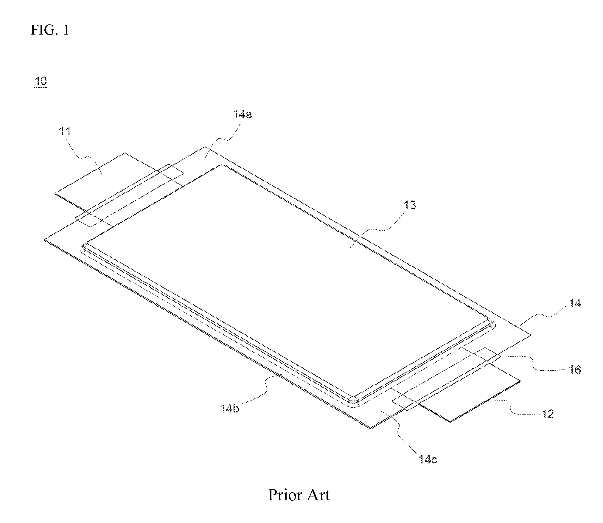
Furthermore, the mechanical strength of the battery case 14 is low.
However, the above-mentioned methods do not provide high sealing force.
Furthermore, when the above-mentioned methods are used, the total weight and the total size of the battery pack are increased, and the assembly process of the battery pack is very complicated.
However, the battery case of the battery may be damaged due to such contact.
According to circumstances, short circuits may occur.
During this procedure, however, the battery case may be damaged.
The damage to the battery case causes leakage of an electrolyte from the battery cell.
Especially in a medium- or large-sized battery pack, in which a plurality of unit cells are stacked one on another, this may cause a serious accident.

Method used


Image

  • Apparatus for manufacturing secondary battery
  • Apparatus for manufacturing secondary battery
  • Apparatus for manufacturing secondary battery

Examples


Embodiment Construction

[0038]Now, preferred embodiments of the present invention will be described in detail with reference to the accompanying drawings. It should be noted, however, that the scope of the present invention is not limited by the illustrated embodiments.

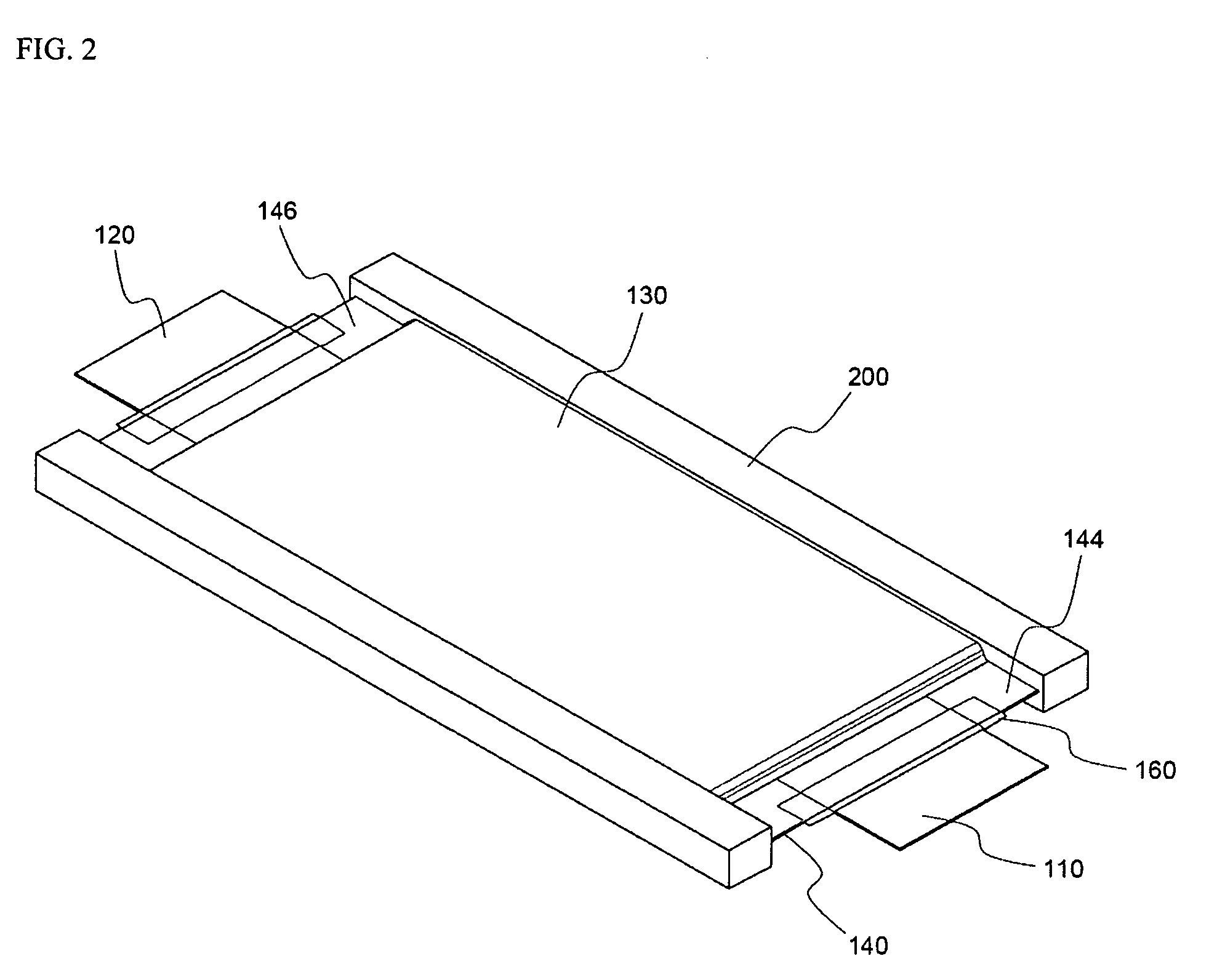
[0039]FIGS. 2 to 4 are perspective views illustrating secondary batteries according embodiments of the present invention, which can be manufactured using an apparatus according to the present invention.

[0040]Referring to FIG. 2, the secondary battery 100 is constructed such that the opposite sides, the upper end part 144, and the lower end part 146 are sealed while an electrode assembly (not shown) is mounted between a two-unit pouch-shaped battery case 140, and cathode and anode leads 110 and 120 protrude from the upper end and the lower end of the battery 100, respectively. Between the electrode leads 110 and 120 and the battery case 140 is interposed a film-shaped sealing member 160 for increasing sealability between the electrode leads 1...


PUM

PropertyMeasurementUnit
heightaaaaaaaaaa
circumferenceaaaaaaaaaa
sizeaaaaaaaaaa

Abstract

Disclosed herein is an apparatus for manufacturing a secondary battery by performing insert injection molding with respect to a portion of a battery cell while the battery cell is located in a mold, wherein the apparatus comprises a pair of upper and lower molds, at which are formed shapes corresponding to the battery cell, the upper and lower molds are provided at the inside surfaces thereof with elastic members, and the elastic members are constructed in a structure in which the elastic members support a cell body of the battery cell and isolate a non-molding region from a molding region while the battery cell is mounted in the upper and lower molds. The secondary battery manufacturing apparatus according to the present invention has the effect of preventing a battery case from being damaged due to the contact between the battery case and the mold when the mold is brought into tight contact with the cell body of the battery cell during insert injection molding to form a molding member at a specific region of the secondary battery, and effectively preventing a material for insert injection molding, which is injected into the molding region, from being injected into the non-molding region.

Description

FIELD OF THE INVENTION[0001]The present invention relates to an apparatus for manufacturing a secondary battery, and, more particularly, to an apparatus for manufacturing a secondary battery by performing insert injection molding with respect to a portion of a battery cell while the battery cell is located in a mold, wherein the apparatus comprises a pair of upper and lower molds, at which are formed shapes corresponding to the battery cell, the upper and lower molds are provided at the inside surfaces thereof with elastic members, and the elastic members are constructed in a structure in which the elastic members support a cell body of the battery cell and isolate a non-molding region from a molding region while the battery cell is mounted in the upper and lower molds.BACKGROUND OF THE INVENTION[0002]Recently, a secondary battery, which can be charged and discharged, has been widely used as an energy source for wireless mobile devices. Also, the secondary battery has attracted cons...

Claims


Application Information

Patent Timeline
Patent Type & Authority Patents(United States)
IPC IPC(8): B29C70/76
CPCH01M2/1005H01M10/0404Y10T29/53135Y02E60/10H01M50/256Y02P70/50B29C45/26
Inventor YOON, JUNILLHAN, JI HOONYANG, HEEKOOK
Owner LG ENERGY SOLUTION LTD
Why Eureka
Eureka Blog
Learn More