High torque, flexible, dual, constant velocity, ball joint assembly for mud motor used in directional well drilling

a directional well and motor technology, applied in the direction of rotary machine parts, mechanical equipment, couplings, etc., can solve the problems of type assemblies that wear prematurely, and achieve the effects of improving wear life, high torque, and increasing the number of contact points

Active Publication Date: 2011-10-11
BENSON TODD
View PDF7 Cites 29 Cited by
  • Summary
  • Abstract
  • Description
  • Claims
  • Application Information

AI Technical Summary

Benefits of technology

[0006]In view of the foregoing, it is a primary objective of the subject invention to provide a high torque, flexible, dual ball joint assembly for improved wear life inside a mud motor housing. Heretofore, mud motors and other high torque, constant velocity, ball joint assemblies are supported in limited radial space inside the mud motor housing. Traditional constant velocity or CV type joint assemblies have 6 to 8 conta

Problems solved by technology

These type assemblies quite often wear prematurely and

Method used


Image

  • High torque, flexible, dual, constant velocity, ball joint assembly for mud motor used in directional well drilling
  • High torque, flexible, dual, constant velocity, ball joint assembly for mud motor used in directional well drilling
  • High torque, flexible, dual, constant velocity, ball joint assembly for mud motor used in directional well drilling

Examples


Embodiment Construction

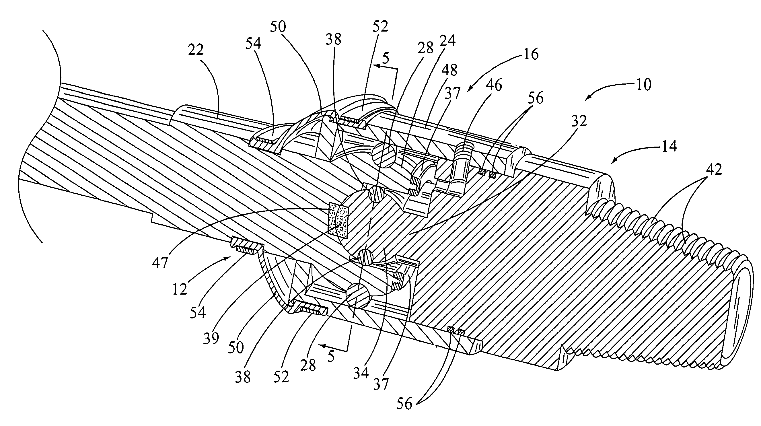
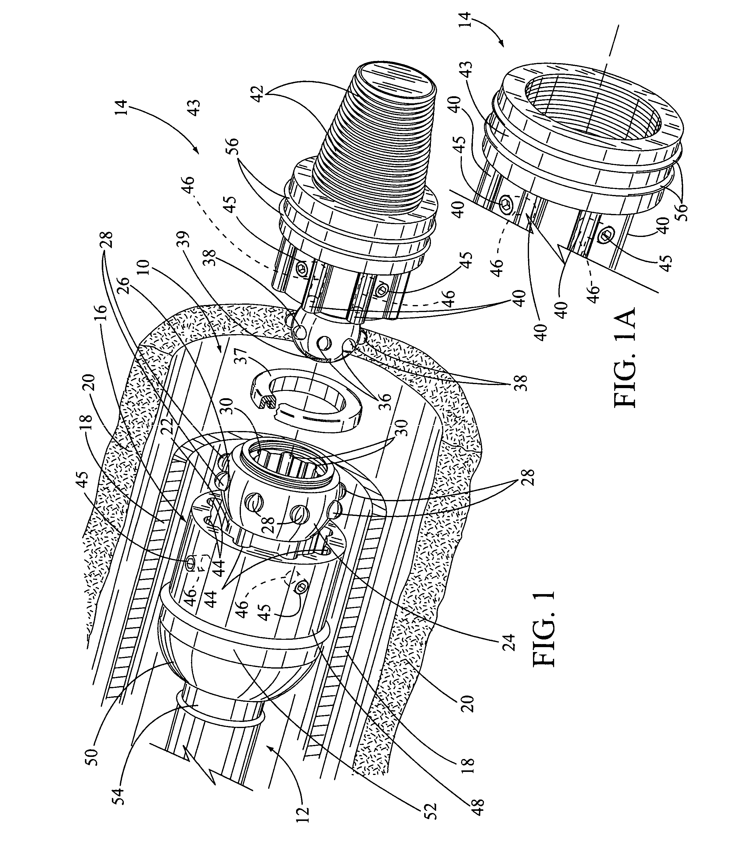
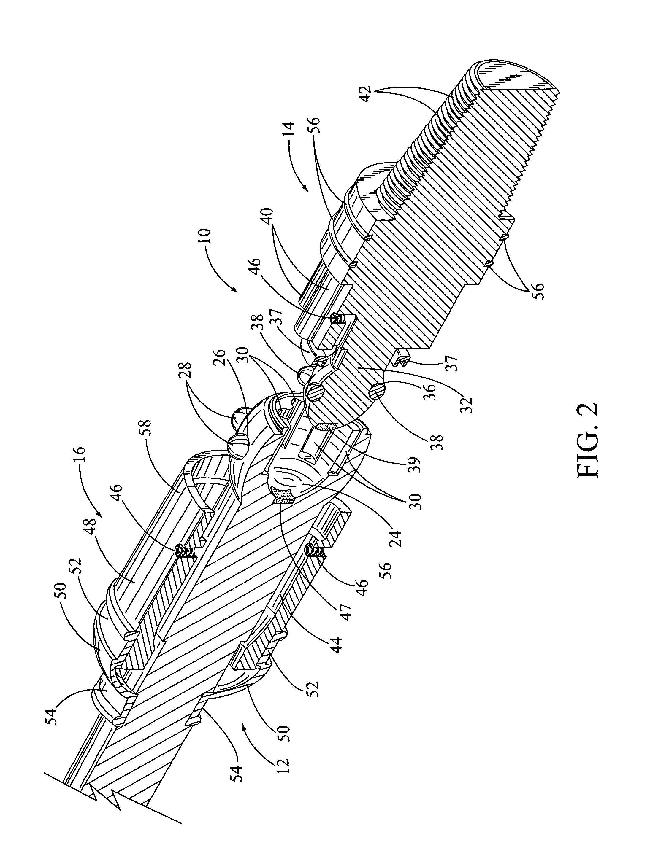
[0019]In FIG. 1, the subject flexible, dual ball joint assembly is shown having general reference numeral 10. The ball joint assembly 10 broadly includes three key elements, which is a drive shaft, having a general reference numeral 12, an annular shaped torque coupler, having a general reference numeral 14, and a sliding torque sleeve, having a general reference numeral 16. The drive shaft 12, the torque coupler 14 and the torque sleeve 16 are part of a down-hole mud motor disposed inside a mud motor housing 18. The housing 18 is shown in cross-section. The complete mud motor is not shown in the drawings. The mud motor is received inside a portion of a drill hole 20, also shown in cross-section.

[0020]The mud motor includes two of the subject ball joint assemblies 10 mounted on opposite ends of the motor. An up-hole ball joint assembly 10 is attached to a up-hole bearing mandrel attached to the rotor and stator mounted inside the housing 18. A down-hole ball joint assembly 10 is att...


PUM


Abstract

A flexible, dual ball joint assembly used for increasing the wear life of a mud motor. The ball joint assembly includes an drive shaft with a drive shaft hollow ball joint. An outer circumference of the hollow ball joint includes a plurality of equally spaced apart drive shaft ball bearings. An inner circumference, inside the hollow ball joint, includes a plurality of equally spaced apart drive shaft grooves. Also, the ball joint assembly includes an annular shaped torque coupler with a torque coupler ball joint. An outer circumference of the torque coupler ball joint includes a plurality of equally spaced apart torque coupler ball bearings. The torque coupler ball bearings are received in the drive shaft grooves for providing lateral movement between the drive shaft and the torque coupler. An outer circumference of the torque coupler next to the torque coupler ball joint includes a plurality of torque coupler lobes equally spaced apart therearound. Further, the ball joint assembly includes a sliding torque sleeve used to secure the drive shaft to the torque coupler during the operation of the ball joint assembly.

Description

BACKGROUND OF THE INVENTION[0001](a) Field of the Invention[0002]This invention relates generally to an improved mud motor used in directional drilling of oil and gas wells and more particularly, but not by way of limitation, to an improved flexible, dual, constant velocity or CV, ball joint assembly used with an drive shaft for increased wear life of a mud motor.[0003](b) Discussion of Prior Art[0004]In directional oil and gas drilling down-hole, a drill pipe string includes a mud motor with a fluid drive rotor inside a stator. The rotor and stator are disposed inside the mud motor's housing and is driven by high pressure fluid. The rotor provides high torque and eccentric, rotation motion for driving the mud motor. The mud motor is used for rotating a drill bit at the end of the drill pipe string. Also inside the mud motor housing is a drive shaft. The drive shaft is used for compensating for eccentric lateral movement from the fluid drive rotor as well as a bend in a mud motor ho...

Claims


Application Information

Patent Timeline
IPC IPC(8): F16D3/221
CPCF16D3/221Y10S464/906
Inventor BENSON, TODD
Owner BENSON TODD
Why Eureka
Try Eureka