Gearless speed reducer or increaser

a technology of speed reducer and increaser, which is applied in the direction of yielding coupling, friction gearing, gearing, etc., can solve the problems of inability to precisely machine gears, inability to accurately machine shafts, and inability to achieve optimal use of traditional gear-based speed reducers, so as to prevent any slippage of balls

Active Publication Date: 2011-10-11
MARMALADE TECH LLC
View PDF19 Cites 9 Cited by
  • Summary
  • Abstract
  • Description
  • Claims
  • Application Information

AI Technical Summary

Benefits of technology

It is therefore an object of the invention to provide a speed reducer or increaser that can achieve very precise tolerances. It is another object of the invention to provide a speed reducer or increaser that can be easily manufactured with few parts.
The system can be uncoupled merely by pivoting the shafts back into alignment so that the balls can rotate freely within the races.
The shafts are held in place in the sleeve against rotation. This can be accomplished in several ways. In one embodiment, the shafts and sleeve are equipped with a series of ball tracks, into which ball bearings are disposed. The ball bearings hold the shaft against rotation in the sleeve. In another embodiment, a keyway is provided. The sleeve can be provided with a longitudinal ridge that slides within a longitudinal groove in the shaft, or vice versa. This also prevents rotation of the shaft within the sleeve. While rotation relative to the sleeve is prevented, the shafts are able to move longitudinally within the sleeve to obtain the proper tension on the speed reducers. This tension is accomplished by springs, which press the shafts and their associated races against the corresponding races in the speed reducers. This ensures that the rotational motion is transmitted through the transmission arrangement, and prevents any slippage by the balls in the transmission arrangement. The sleeve is also preferably equipped with stop elements that prevent excessive axial movement of the shafts within the sleeve.

Problems solved by technology

A problem with this arrangement however, is that it is very difficult to create precisely machined gears that have no play between them.
This play leads to inaccuracies in the machine in which the shafts are disposed.
With operations that require very precise positioning, such as with jewelry making or circuit board operations, the traditional gear-based speed reducers are not optimal.

Method used


Image

  • Gearless speed reducer or increaser
  • Gearless speed reducer or increaser
  • Gearless speed reducer or increaser

Examples


Embodiment Construction

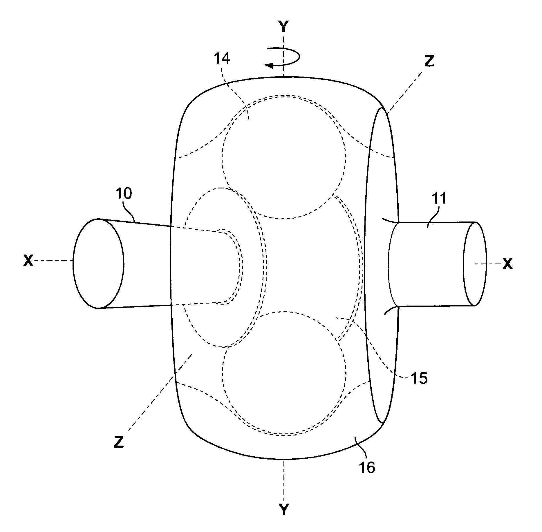
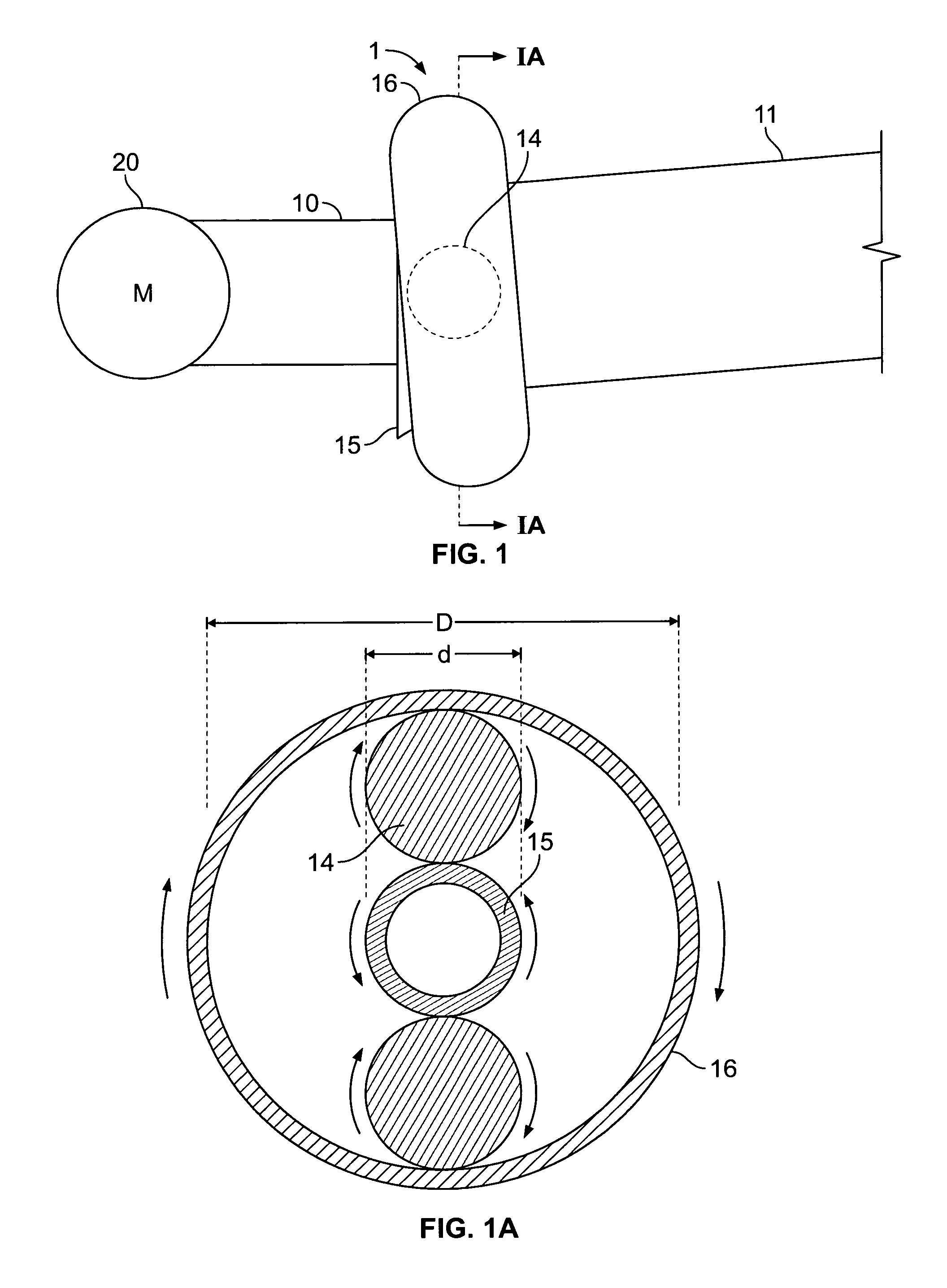
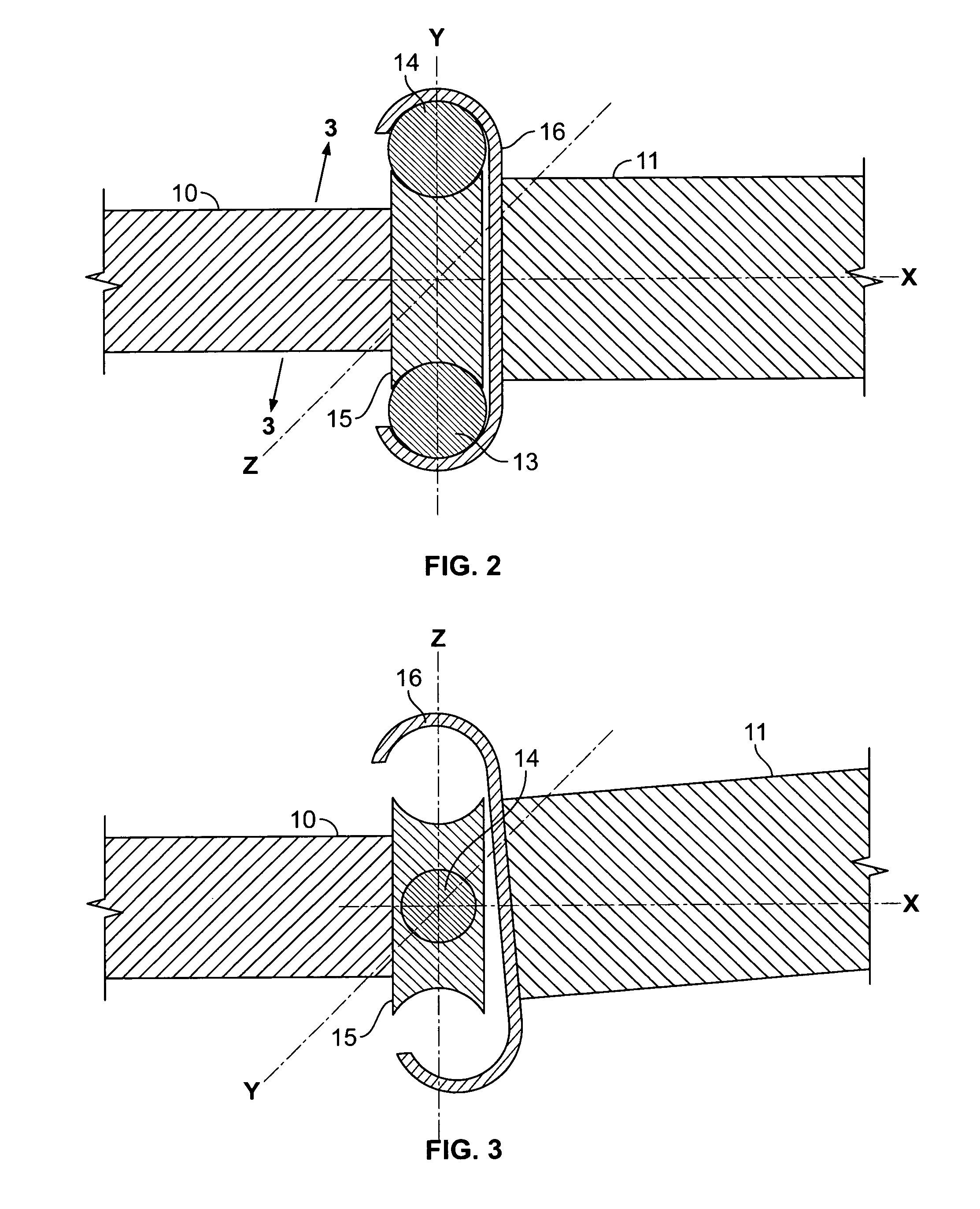
Referring now in detail to the drawings, FIG. 1 shows a top view of the transmission arrangement according to one embodiment of the invention. The transmission arrangement 1 comprises an input shaft 10, connected to an inner race 15, and an output shaft 11, connected to an outer race 16. Between the two races are two ball bearings 14, shown in dotted lines in this view. A motor 20 is connected to input shaft 10. Inner race 15 is disposed angularly offset to outer race 16, so that ball bearings 14 are held in a pocket between the races with no play. The offset occurs by pivoting one of the races around the y-axis shown in FIGS. 2-3. The degree of offset required to hold the balls depends on the curvature of the raceways, the size of the balls, and the amount of play of the balls in the races prior to being offset. This pivoting creates a pocket to accommodate the balls, and reduces the clearance on both sides of each ball 14 to eliminate the ability for the ball to slide along the ra...


PUM


Abstract

A gearless speed reducer or increaser consists of an input shaft, an output shaft, and a motor connected to the input shaft. There is an external race connected to one of the shafts, and an internal race attached to the other shaft. Two ball bearings are disposed between the races. After the ball bearings have been inserted, the shafts are tilted relative to each other so that the balls become fixed in pockets created between the races and cannot slide within the races. Rotating one of the shafts thus rotates the other shaft, since the balls do not slip but only rotate between the races. The system acts as a speed reducer or increaser due to the different diameters of the inner and outer races. The system can be uncoupled by pivoting the shafts back into alignment so that the balls can slide freely within the races.

Description

BACKGROUND OF THE INVENTION1. Field of the InventionThis invention relates to a gearless speed reducer or increaser. In particular, this invention relates to a device that transmits rotational power from an input shaft to an output shaft, so that the second shaft rotates at a greater or lesser speed than the input shaft, using a set of ball bearings, and without using gears.2. The Prior ArtIn traditional devices used to increase or reduce speed, the connection between the input shaft and the output shaft is made through the use of gears. An internal gear on one shaft cooperates with an external gear on the other shaft to transmit the power from one shaft to the other. If the two shafts have different radii, the speed of one shaft will differ from that of the other shaft.A problem with this arrangement however, is that it is very difficult to create precisely machined gears that have no play between them. This play leads to inaccuracies in the machine in which the shafts are disposed...

Claims


Application Information

Patent Timeline
Patent Type & Authority Patents(United States)
IPC IPC(8): F16H13/04
CPCF16D3/20F16H13/04F16H13/14
Inventor PAWLOSKI, JOHN
Owner MARMALADE TECH LLC
Why Eureka
Try Eureka