Motor with sheet-like coil

a brushless spindle motor and coil technology, applied in the direction of windings, mechanical energy handling, dynamo-electric components, etc., can solve the problems of unsatisfactory vibration, hard to increase the torque of the slotless spindle motor, and difficult to increase the number of coil turns, etc., to achieve stable rotation performance

Inactive Publication Date: 2011-10-11
MINEBEA CO LTD
View PDF7 Cites 24 Cited by
  • Summary
  • Abstract
  • Description
  • Claims
  • Application Information

AI Technical Summary

Benefits of technology

The present invention has been made in the light of the problems described above, and it is a primary object of the present invention to provide a radial gap type slotless motor, in which if a fine pattern coil (FP coil) is used as a sheet-like coil, the portions each located between two adjacent individual coils in the film pattern coil are free from cracks, the entire sheet-like coil is fixed tightly to the back yoke, and therefore a stable rotation performance is achieved.
According to the present invention, there is provided a radial gap type slotless motor, in which if a fine pattern coil (FP coil) is used as a sheet-like coil, the portions each located between two adjacent individual coils in the film pattern coil are free from cracks, the entire sheet-like coil is fixed tightly to the back yoke, and therefore a stable rotation performance is achieved.

Problems solved by technology

However, with increasing magnetic recording density, the slot type spindle motor tends to suffer from cogging which is generated by the presence of the salient poles and which causes an undesirable vibration.
Therefore it is hard to increase torque in the slotless spindle motor 71.
However, in a typical sheet coil which is made such that a single-layered coil is formed on a flexible substrate by printing or etching, it is hard to increase the number of coil turns, which means it is difficult to achieve a high-density conductor circuit with coil having a high wiring occupation ratio.
However, it turns out that when such a thick film fine pattern coil is used in a radial gap type spindle motor which is expected to generate a larger torque than the above described axial gap type spindle motor, there occurs a problem that when the strip-shaped thick film fine pattern coil, which includes a plurality of rectangular individual coils arrayed in a straight line, is bound around the outer cylindrical circumference of a back yoke, the thick film fine pattern coil does not make a tight contact with the entire circumferential surface of the back yoke thus resulting in unintentionally and undesirably generating gaps partly therebetween.
This is because the thick film fine pattern coil, when rolled up, undergoes an inhomogeneous deformation, for example, may be bent between every adjacent individual coils thus failing to be rolled up in a good shape entirely with a uniform curvature.
Also, torque ripple is generated, and consequently it is very hard to achieve a stabilized rotation performance.
Also, depending on the degree of deformation, the thick film fine pattern coil is possibly cracked at portions each located between two adjacent individual coils, in which case the thick film conductor may be broken or rusted.
Further, gas or dust may leak from the cracked portions.
The problem that the thick film fine pattern coil, when rolled up, is deformed and eventually cracked at the portions between two adjacent individual coils as described above is attributed to the difference in stiffness between the metal material (thick film conductor), such as copper, for forming the individual coils and the resin material (insulation layer between conductors) present between the adjacent individual coils.
On the other hand, the thick film fine pattern coil entirely has relatively large stiffness, so that when the thick film fine pattern coil is rolled up to sit tightly on the outer cylindrical surface of the back yoke (especially if its diameter is small), both ends of the thick film fine pattern coil are possibly caused to spring back.

Method used


Image

  • Motor with sheet-like coil
  • Motor with sheet-like coil
  • Motor with sheet-like coil

Examples


first embodiment

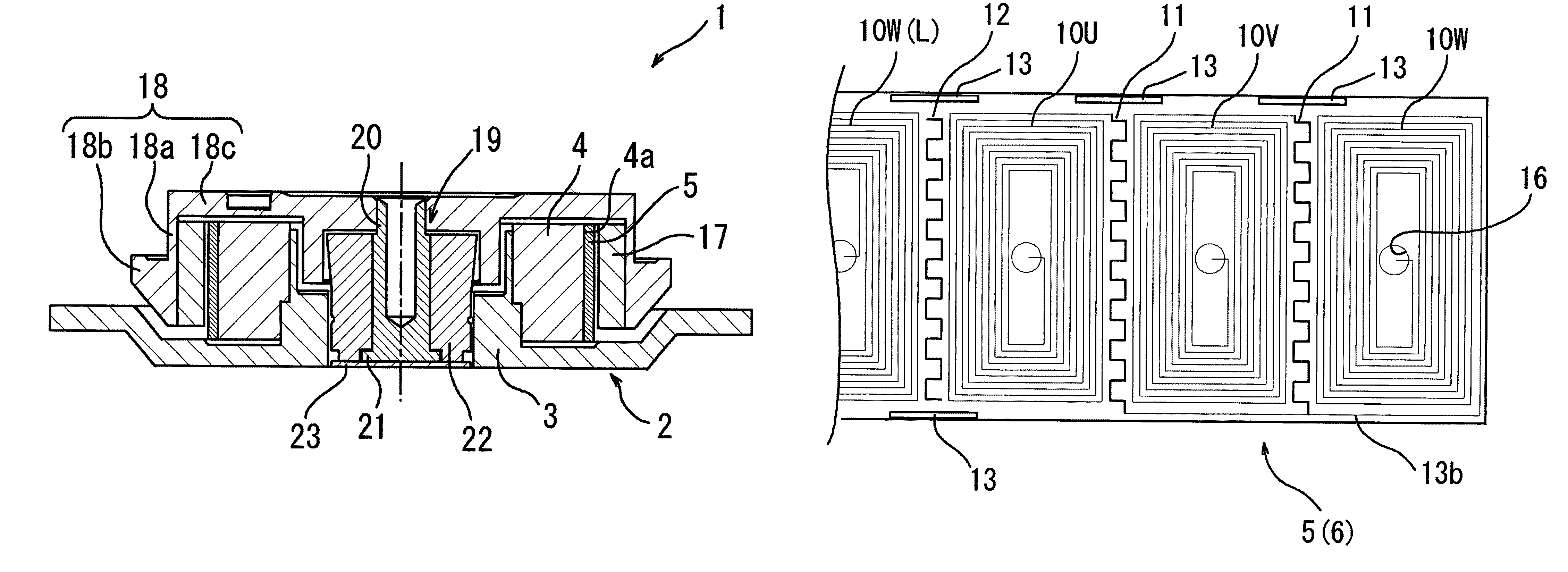
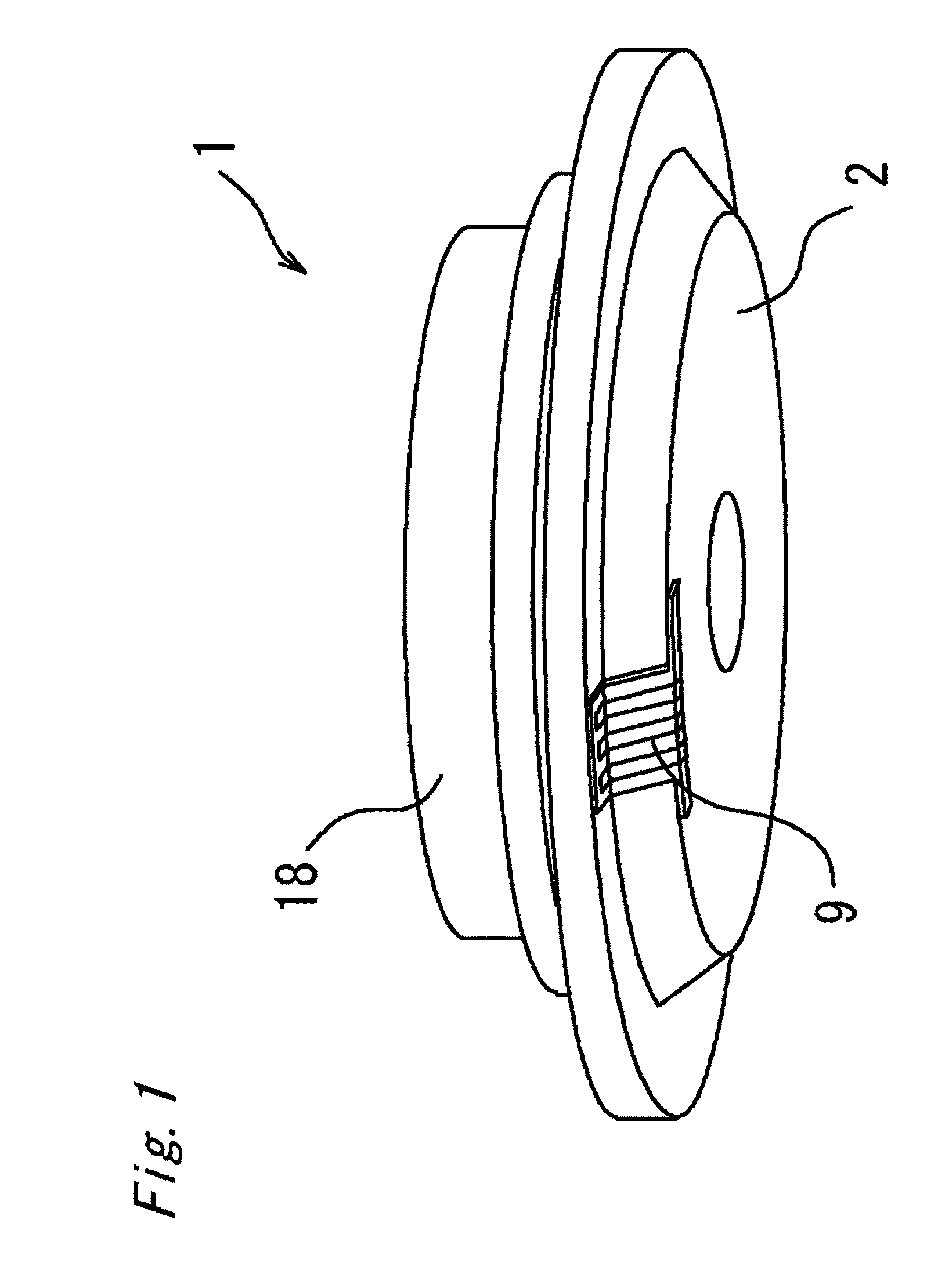
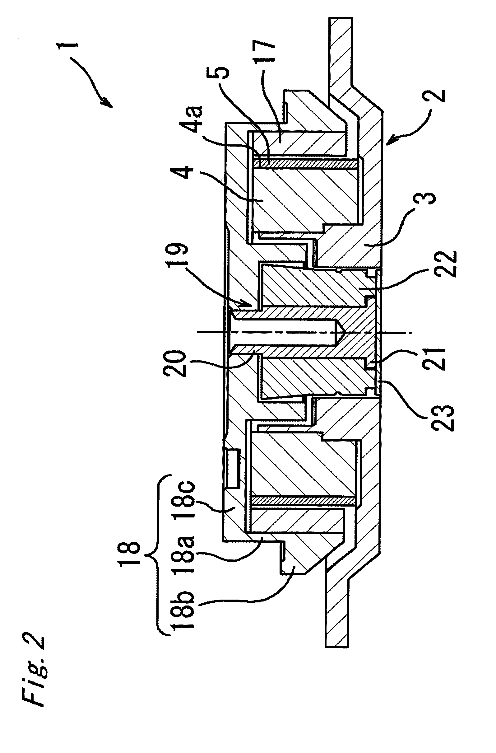
the present invention will be described with reference to FIGS. 1 and 2. Referring to FIGS. 1 and 2, a spindle motor 1 is a radial gap type slotless spindle motor, in which a dish-like housing 2 is disposed at the lower side in the figures, a hollow circular cylindrical boss 3 formed integrally with the housing 2 by aluminum die casting is disposed substantially vertically at the center part of the housing 2 so as to extend toward the upper side in the figures, and in which a terminal 7 (not shown in FIG. 2) to supply electric power to a sheet-like coil 5 (to be described later) is disposed at the lower surface (bottom surface) of the housing 2.

A hollow circular cylindrical stator yoke 4 having no salient poles is fixedly attached at the outer circumference of the boss 3. The stator yoke 4 is made of a soft magnetic steel plate (an electromagnetic steel plate, for example, a cold-rolled steel plate (SPC), an electro galvanized steel plate (SEC), or a silicon steel plate). In conside...

second embodiment

the present invention will be described with reference to FIGS. 8 and 9. FIG. 8 shows a sheet-like coil (FP coil) 25 fixedly attached to an outer circumferential surface 24a of a stator yoke 24. FIG. 9 shows the sheet-like coil 25 developed and viewed from the front side. A spindle motor according to the second embodiment differs from the spindle motor 1 according to the first embodiment in the structure of the stator yoke 24 and the sheet-like coil 25.

Specifically, referring to FIG. 8, the stator yoke 24 includes a slit 24b formed at the outer circumferential surface 24a so as to axially extend all the way through. The slit 24b is so configured (with respect to a width and a depth) as to allow fold portions 30 (to be described later) of the sheet-like coil 25 to be engaged or inserted therein.

On the other hand, the sheet-like coil 25 includes a body portion 26 having a strip-shape, a terminal 27 (not shown in FIG. 8) extending from one end portion of the body portion 26, and the af...

third embodiment

the present invention will be described with reference to FIG. 10. FIG. 10 shows an enlarged view of a profile cross section of a part of a sheet-like coil 45 (an individual coil 50). A spindle motor according to the third embodiment differs from the spindle motor 1 according to the first embodiment in aspect ratio between a thick film conductor 49a and a thick film conductor 49b formed at a front surface 48a and a rear surface 48b of a core sheet 48, respectively.

In the sheet-like coil 5 of the first embodiment, as described above, the turn segment number (the turn number of the individual coil 10), the pitch P and the aspect ratio (height H / width W ) of the thick film conductor 9 are set substantially identical between the front individual coil 10a and the rear individual coil 10b. On the other hand, in the third embodiment, the aspect ratio of a thick film conductor 49b (hereinafter referred to as rear thick film conductor 49b) constituting a rear individual coil 50b is set small...


PUM


Abstract

A spindle motor includes: a stator yoke having a circular cylinder shape; a rotor magnet disposed opposite to the stator yoke with an air gap therebetween; a sheet-like coil disposed at a surface of the stator yoke opposing the rotor magnet; and a bearing structure, wherein the sheet-like coil includes a plurality of individual coils having a spiral-shape and arrayed in a circumferential direction, and a pattern made of a same material as the individual coils and disposed between two adjacent individual coils.

Description

FIELD OF THE INVENTIONThe present invention relates to a slotless brushless spindle motor, and more particularly to a spindle motor employed in a magnetic disk apparatus for driving a magnetic disk.BACKGROUND OF THE INVENTIONConventionally, a slot type spindle motor, in which a yoke (stator yoke) provided with salient poles is used in a stator and which has excellent magnetic efficiency, is generally employed in magnetic disk apparatuses. However, with increasing magnetic recording density, the slot type spindle motor tends to suffer from cogging which is generated by the presence of the salient poles and which causes an undesirable vibration. To prevent such a cogging, a slotless spindle motor is disclosed in which a sheet-like coil is fixedly attached at the outer circumferential surface of a stator yoke which is free from salient poles (refer to, for example, Japanese Patent Application Laid-Open No. 2002-27720).FIG. 13 is a perspective view of a slotless spindle motor 71 disclos...

Claims


Application Information

Patent Timeline
Patent Type & Authority Patents(United States)
IPC IPC(8): H02K3/26
CPCH02K3/26H02K3/47H02K21/222
Inventor SUZUKI, YUZURUTAKAHASHI, YUUKIFURUYA, MIYUKI
Owner MINEBEA CO LTD
Why Eureka
Try Eureka