Radio communication system that uses a MIMO receiver

a radio communication system and receiver technology, applied in the field of receivers, receiving methods, radio communication systems, etc., can solve the problems of disproportionate addition of error signals, degradation of signal separation characteristics, and exponential increase in computation load, and achieve the effect of superior signal separation characteristics

Inactive Publication Date: 2011-10-11
NEC CORP
View PDF23 Cites 8 Cited by
  • Summary
  • Abstract
  • Description
  • Claims
  • Application Information

AI Technical Summary

Benefits of technology

It is an object of the present invention to provide a MIMO receiver, reception method, and radio communication system that can obtain a superior signal separation characteristic regardless of differences between the levels of multipath signals.
The present invention enables optimum combining of the multipath signals for the signal of each transmission antenna by means of a combining method that takes into consideration differences in the levels of multipath signals, and further allows a superior signal separation characteristic to be obtained regardless of the differences in level of multipath signals.
In addition, the MIMO receiver of the present invention may further include a whitening filter for whitening the noise in the signals in which multipaths have been combined by the multipath linear combining unit and for providing this whitened signal to the maximum likelihood detector.
The maximum likelihood detection process is therefore carried out after whitening noise after combining of the multipath signals, with the result that a superior signal separation characteristic can be realized in which the effect of noise is mitigated.

Problems solved by technology

MLD has superior characteristics to MMSE and VBLAST but has the disadvantage that the increase in the number of transmission antennas and the number of modulation multivalues brings with it an exponential increase in computation load.
In a MIMO receiver of the prior art, the influence of multipath interference is not taken into consideration in the calculation of error signals, and as a result, there is a disproportionately large addition of the error signal of multipaths having a low level and a consequent degradation of the signal separation characteristic.
On the other hand, the other MIMO receiver of the prior art shown in FIG. 4, performs the MLD process using signals in which despread signals undergo QH conversion, but because the transmission channel matrix is subjected to direct QR decomposition, the operation is principally equivalent to that of the MIMO receiver of FIG. 2, and is therefore subject to the same problem.

Method used


Image

  • Radio communication system that uses a MIMO receiver
  • Radio communication system that uses a MIMO receiver
  • Radio communication system that uses a MIMO receiver

Examples


first embodiment

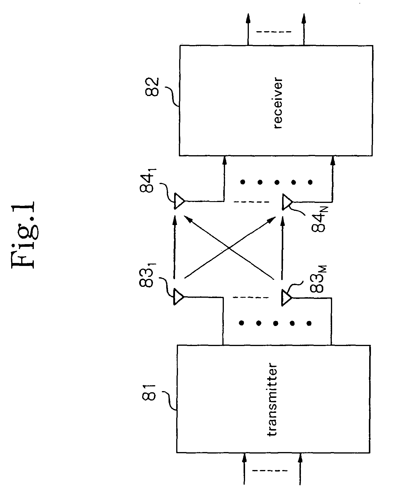
FIG. 6 is a block diagram showing the configuration of the radio communication system according to the This system uses MIMO (Multiple Input Multiple Output) multiplexing, and in this case, the number of transmission antennas is M (where M is an integer equal to or greater than 1) and the number of reception antennas is N (where N is an integer equal to or greater than 1).

Referring to FIG. 6, the radio communication system includes transmitter 11 and receiver 12. Transmitter 11 includes transmission antennas 131-13M, and receiver 12 includes reception antennas 141-14N.

Transmitter 11 transmits a different signal from each of the plurality of transmission antennas 131-13M at the same frequency and at the same time. Receiver 12 uses the plurality of reception antennas 141-14N to receive the signals that are transmitted from transmitter 11, and demodulates M signals from the received signals by means of a signal separation process.

FIG. 7 is a block diagram showing the configuration of ...

third embodiment

Minimum Means Square Error (MMSE) and Zero Forcing (ZF) are combining methods (equalizing methods) that take into consideration the suppression of multipath interference. In the third embodiment, an example is shown in which MMSE or ZF is used as the method of combining multipaths.

The radio communication system of the third embodiment is of the same configuration as in the first embodiment shown in FIG. 6.

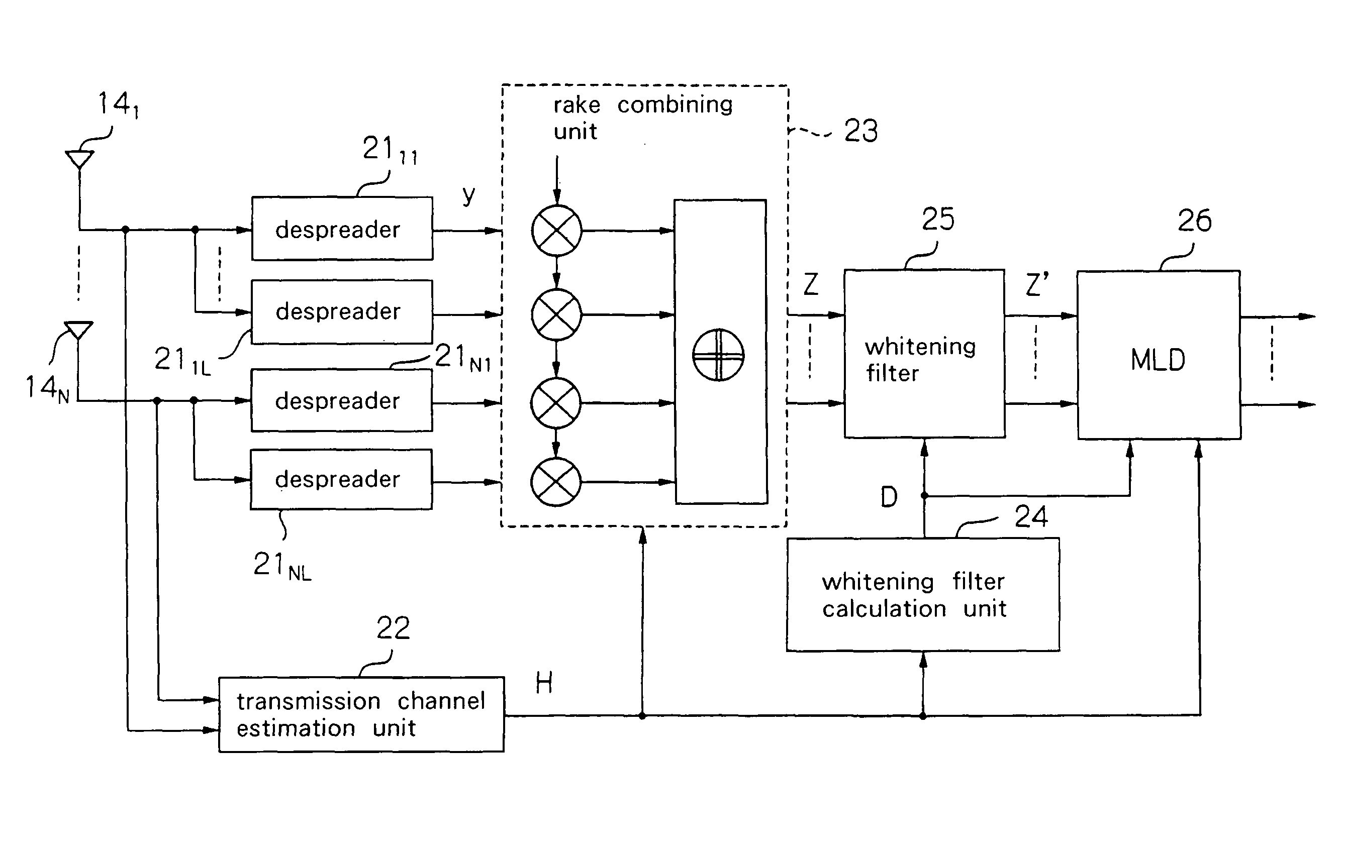
FIG. 11 is a block diagram showing the configuration of the receiver according to the third embodiment. Referring to FIG. 11, receiver 12 according to the third embodiment includes: reception antennas 141-14N, transmission channel estimation unit 22, equalizing weight calculation unit 61, MMSE / ZF equalizer 62, despreaders 631-63M, whitening filter calculation unit 64, whitening filter 65, and MLD unit 66.

Transmission channel estimation unit 22 takes as input the signals that are received at reception antennas 141-14N and uses a known pilot signal that is contained in these received...

fourth embodiment

Explanation next regards the fourth embodiment with reference to the accompanying figures.

In the above-described third embodiment, as an example in which the suppression of multipath interference is considered, a configuration was shown in which the MLD process was performed after implementing equalizing filtering based on the MMSE or ZF method for multipath interference. However, various other examples can also be considered as configurations that take into consideration the suppression of multipath interference. In the fourth embodiment, an example of a configuration is shown in which the results of first demodulating CDMA received signals (primary demodulation) are used to reproduce multipath signals, and signals obtained by eliminating the multipath interference from these multipath signals are then used to perform rake combining and the MLD process.

The radio communication system of the fourth embodiment is of the same configuration as in the first embodiment shown in FIG. 6.

FIG...


PUM


Abstract

A receiver uses a transmission channel matrix to obtain a superior signal separation characteristic regardless of differences in levels of multipath signals. A multipath linear combining unit performs linear combining of the multipaths in received signals of the reception antennas by means of the transmission channel matrix between the plurality of transmission antennas and the plurality of reception antennas. A maximum likelihood detector compares signals in which multipaths have been combined by the multipath linear combining unit with reception replicas that have been found using the transmission channel matrix to estimate the transmitted signals of each of the transmission antennas.

Description

BACKGROUND OF THE INVENTION1. Field of the InventionThe present invention relates to a receiver, a receiving method, and a radio communication system that are used in communication realized by MIMO, and more particularly to a receiver, a receiving method, and a radio communication system in which MIMO signals are demodulated by means of maximum likelihood detection (MLD) from signals that are received using a plurality of reception antennas.2. Description of the Related ArtRadio communication methods in next-generation mobile communication demand high-speed data transmission. MIMO (Multiple Input Multiple Output) multiplexing is receiving attention as a technology for realizing high-speed data transmission. MIMO is a technology for transmitting a plurality of signals from a plurality of transmission antennas at the same frequency and the same time, receiving these signals using a plurality of reception antennas, and then demodulating (implementing signal separation of) the plurality...

Claims


Application Information

Patent Timeline
Patent Type & Authority Patents(United States)
IPC IPC(8): H04B7/02H04B1/00H04L27/06H04J99/00H04B1/707H04B1/7107H04B1/7115H04B7/04H04B7/08
CPCH04B7/0848
Inventor YOSHIDA, SHOUSEI
Owner NEC CORP
Why Eureka
Try Eureka