Pacing lead and method for pacing in the pericardial space

a pericardial space and pacing lead technology, applied in the direction of internal electrodes, transvascular endocardial electrodes, therapy, etc., can solve the problems of difficult stabilization, inability to access the chamber of the heart or a specific location using a transvenous approach, and inability to meet the needs of patients, so as to enhance the position stability of the electrodes

Inactive Publication Date: 2011-10-11
WORLEY SETH
View PDF45 Cites 41 Cited by
  • Summary
  • Abstract
  • Description
  • Claims
  • Application Information

AI Technical Summary

Benefits of technology

[0009]The pacing lead of the various embodiments of the present invention substantially addresses the aforementioned problems of conventional designs by providing lead shapes, methods of fixation, and methods of pacing lead deployment that assure that the electrodes of the lead are firmly in electrical conductive contact with the epicardial surface and the lead is positionally stable. The lead of the present invention may thereby enable relatively low pacing voltages, generally 3 volts or less. In an embodiment, the improved stability and pacing is accomplished when a resilient fixation structure in the form of a helix, loop, or other resilient structure is compressed between the parietal and visceral pericardium when disposed in the pericardial space. The biasing force exerted by compression of the helical fixation element biases electrodes on the lead body against the visceral pericardium thereby improving electrical conductivity between the myocardium and the electrodes, and providing a degree of positional stability. Positional stability of the lead may be further enhanced in some embodiments with bio-compatible adhesive introduced at desired locations to adhere the lead body to surrounding tissues.
[0010]In an embodiment, the lead has a proximal portion and a distal portion comprising a resilient fixation element extending from the proximal portion. The proximal portion includes a pair of electrodes. The compression fixation element may be preformed in a helix or other shape enabling resiliency. The height or width dimension of the fixation element is predetermined so as to be larger than space between the visceral and parietal pericardium. When the lead is advanced into the pericardial space, the fixation element is compressed by the walls of the heart defining the pericardial space, specifically the visceral pericardium and the myocardium. The electrodes of the pacing portion, which may be disposed proximate the fixation element, are biased against the myocardium by the resilience of the fixation element. Electrical conductivity between the electrodes and the myocardium is thereby improved, along with lead stability and pacing and sensing thresholds.

Problems solved by technology

In some cases, however, the chamber of the heart or a specific location on the chamber of the heart is not accessible using a transvenous approach and must be placed surgically.
These prior leads, however, all have certain drawbacks making them not entirely satisfactory.
These prior helical leads, however, are sometimes difficult to stabilize and may be prone to “overturn” or rotate about the longitudinal axis of the lead when in place, thereby interrupting electrical contact of the electrodes.
Further, the present inventor recognizes that prior art leads, fixation and stabilization methods are not entirely suitable for leads introduced into the pericardial space through the venous system.

Method used


Image

  • Pacing lead and method for pacing in the pericardial space
  • Pacing lead and method for pacing in the pericardial space
  • Pacing lead and method for pacing in the pericardial space

Examples


Embodiment Construction

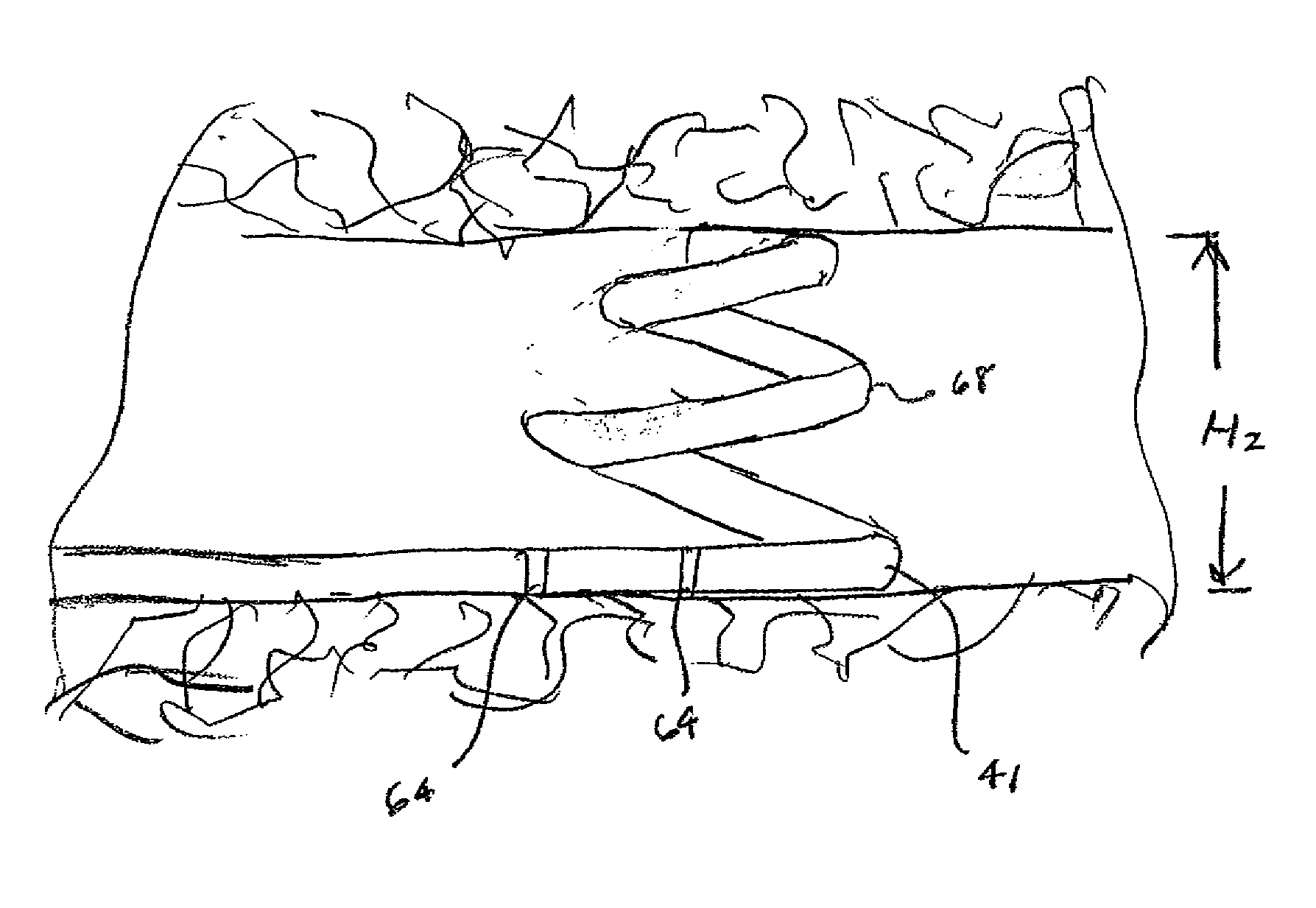
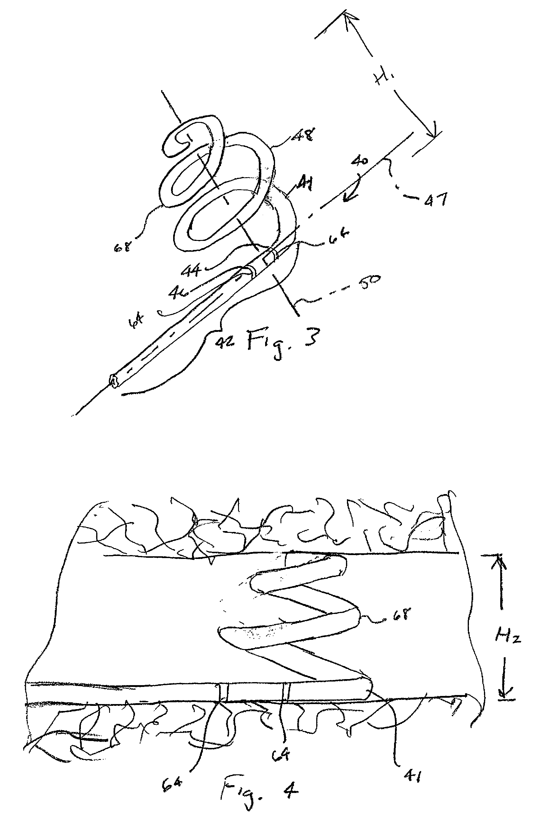
[0065]Referring to FIGS. 3-6, a pacing lead 40 according to the various embodiments of the present invention generally includes a lead body 41 with a proximal lead portion 42 having a pair of electrodes 44, 46, and presenting a longitudinal lead axis 47, and a resilient fixation portion 48. Resilient fixation portion 48 is preformed in a helical configuration, with the helix being generally symmetrical about a fixation portion axis 50. Fixation portion axis 50 may be generally normal to longitudinal lead axis 47 so that resilient fixation portion 48 extends laterally relative to proximal lead portion 42. Pacing leads are generally known in the art and are disclosed in U.S. Pat. No. 6,321,123 to Morris et al. and U.S. Pat. No. 5,683,445 to Swoyer, both of which are incorporated herein by reference in their entirety.

[0066]In the embodiment depicted in FIG. 6, lead body 41 generally includes inner body 52 with defining central lumen 54, inner conductor 56 which is electrically coupled ...


PUM


Abstract

A pacing lead for implantation in the pericardial space includes an elongated lead body, a compression fixation element, and at least one electrode on either the lead body or the fixation element. The fixation element defines a resilient structure, and is positioned and dimensioned so that when the lead is disposed in the pericardial space, the resilient fixation element is compressed between the parietal and visceral pericardium, thereby biasing the electrode against the myocardium and providing positional stabilization to the lead. Further positional stability may be provided mechanically with structures enabling the application of adhesive or with fixation screw or tine elements.

Description

RELATED APPLICATIONS[0001]This application claims the benefit of U.S. Provisional Patent Application No. 60 / 825,139, entitled PACING LEAD AND METHOD FOR PACING IN THE PARICARDIAL SPACE, filed Sep. 10, 2006, and hereby fully incorporated herein by reference.FIELD OF THE INVENTION[0002]The present invention relates generally to pacing leads. More particularly, the present invention relates to pacing leads for implantation between the visceral and parietal pericardium of the heart.BACKGROUND OF THE INVENTION[0003]As depicted in FIGS. 1 and 2, the human heart 30 is contained in the mediastinum 32 within a conical sac of serous membrane called the pericardium 34. There are generally two layers to pericardium 34; the fibrous pericardium 35 and the serous pericardium 36. The fibrous pericardium 35 is a superficial layer comprising dense connective tissue and it encloses serous pericardium 36. The serous pericardium 36 itself has two layers. The layer adjacent the fibrous pericardium is the...

Claims


Application Information

Patent Timeline
Patent Type & Authority Patents(United States)
IPC IPC(8): A61N1/375
CPCA61N1/0587A61N2001/0585
Inventor WORLEY, SETH
Owner WORLEY SETH
Why Eureka
Try Eureka