Sensor plug for combined pressure and temperature measurement

a technology of combined pressure and temperature measurement, which is applied in the direction of instruments, heat measurement, heating types, etc., can solve the problems of reducing the reproducibility of the proposed measurement concept, increasing assembly time and assembly costs, and not ensuring the pressure tightness, so as to achieve good robustness and good reproducibility

Active Publication Date: 2011-10-18
ROBERT BOSCH GMBH
View PDF23 Cites 23 Cited by
  • Summary
  • Abstract
  • Description
  • Claims
  • Application Information

AI Technical Summary

Benefits of technology

[0011]The present invention therefore provides a sensor plug for pressure and temperature measurement of a fluid medium, in particular for use in the coolant circuit of a climate control system of a motor vehicle, which plug avoids the above-described disadvantages of the existing art and ensures good robustness simultaneously with good reproducibility of both the pressure signal and temperature signal. The sensor plug is usable in particular for service in CO2 climate control systems.
[0015]The proposed disposition of the sensor plug with the inclined temperature sensing element orifice axis makes possible temperature measurement with increased accuracy, since centered temperature measurement (or temperature measurement in the vicinity of the center) is now possible despite the central disposition of the pressure sensor. It is thereby possible to implement simultaneously a physically small sensor plug that has a centered pressure sensor but nevertheless exhibits high accuracy in both pressure and temperature measurement.
[0016]In particular, the sensor plug can have a temperature sensor element, preferably an NTC resistor. The temperature sensing element orifice axis is preferably disposed so that it intersects the sensor body axis in the region of the temperature sensor element. For example, the temperature sensing element orifice (having corresponding orifice shoulders or the like) can be configured such that the temperature sensor element is correspondingly disposed and / or retained. A centered disposition of the temperature sensor element can thereby be guaranteed. The term “in the region” also encompasses certain tolerances, for example a deviation of the temperature sensor element from the intersection point between sensor body axis and temperature sensing element orifice axis of no more than 20% of the spatial extension of the temperature sensor element. Alternatively or additionally, the disposition selected can also be such that the intersection point between sensor body axis and temperature sensing element orifice axis is still located in the region of the spatial extension of the temperature sensor element.
[0020]The sensor plug described above, in one of the embodiments presented, can be additionally improved by a variety of refinements that become particularly advantageously apparent in combination with the above-described inclinations of the orifice axes. For example, the sensor body can have an external thread for threading into a sensor plug orifice, as well as a conical seal disposed at its end pointing toward the fluid medium. In contrast to known assemblages, such as the assemblage known, for example, from Stefan Butzmann (ed.), “Sensorik im Kraftfahrzeug” [Sensor technology in motor vehicles], expert Verlag, 2006, pp. 73-81, this disposition of the sealing cone at the end of the sensor plug pointing toward the fluid medium has the advantage that the conical seal can be protected by the external thread from water splashes and from atmospheric moisture. Corrosion at the conical seal can thereby be greatly reduced or eliminated.
[0021]In addition, at least one discharge groove, preferably two discharge grooves, can be provided in the external thread, this / these groove(s) being configured to vent an overpressure when the external thread is threaded into the sensor plug orifice. This at least one discharge groove is easy to integrate in terms of design engineering, and greatly simplifies the threading-in operation.
[0024]Accordingly, a method for manufacturing a sensor plug of this kind is also proposed, in which method the insert is manufactured using the powder-metallurgy process, the threaded piece being manufactured not necessarily by powder metallurgy but also, for example, in conventional fashion (e.g. by removal of material). After manufacture of the insert and threaded piece, the insert is inserted into the threaded piece, and the insert and threaded piece are joined to one another in positively engaged and pressure-tight fashion. The use of laser welding methods has proven particularly successful. It is possible in this fashion to manufacture, economically, a sensor plug that is optimized for the use described, in particular in CO2 climate control systems; that is physically small and easy to install; that can be produced even in large quantities; and that nevertheless exhibits, as compared with the existing art, high accuracy in measuring the temperature of the fluid medium.

Problems solved by technology

Comparatively complex seals for the membrane are used, using conventional O-rings that easily become embrittled when operated over longer periods (especially with the aforementioned higher temperature loads), so that pressure tightness is not guaranteed over the longer term.
A further disadvantage is the complex construction of the seals, which necessitates multiple working steps and thus greatly increases assembly time and assembly costs.
A further disadvantage of the proposed approach is that the proposed measurement concept, in particular the temperature measurement concept, is comparatively inaccurate, since the pressure measurement membrane, with the thermistor on it, is located relatively far away from the measured medium.
This approach entails, however, the disadvantage that the sensor is very sensitive especially in the membrane region, so that it many cases a protective shield must be mounted in front.
A further disadvantage of the approach presented in German patent document DE 101 09 095 is that the accuracy of the pressure and / or temperature measurements using the proposed assemblage can vary greatly, under otherwise identical conditions, depending on the installation location of the combined sensor.
The installation problem just described is aggravated by the fact that in usual climate control systems such as those provided, for example, in a motor vehicle, the diameters of the coolant tubes are very small.
A central disposition of the temperature sensor is, however, difficult or impossible in many cases because of the central disposition (preferred for reasons of installation space) of the pressure sensor.

Method used


Image

  • Sensor plug for combined pressure and temperature measurement
  • Sensor plug for combined pressure and temperature measurement
  • Sensor plug for combined pressure and temperature measurement

Examples


Embodiment Construction

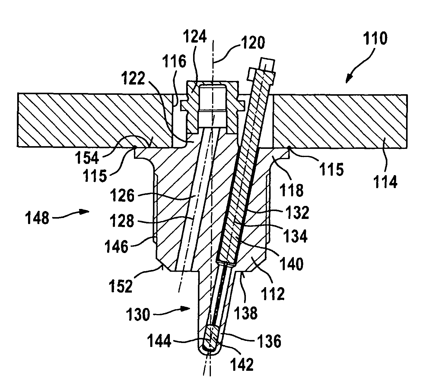
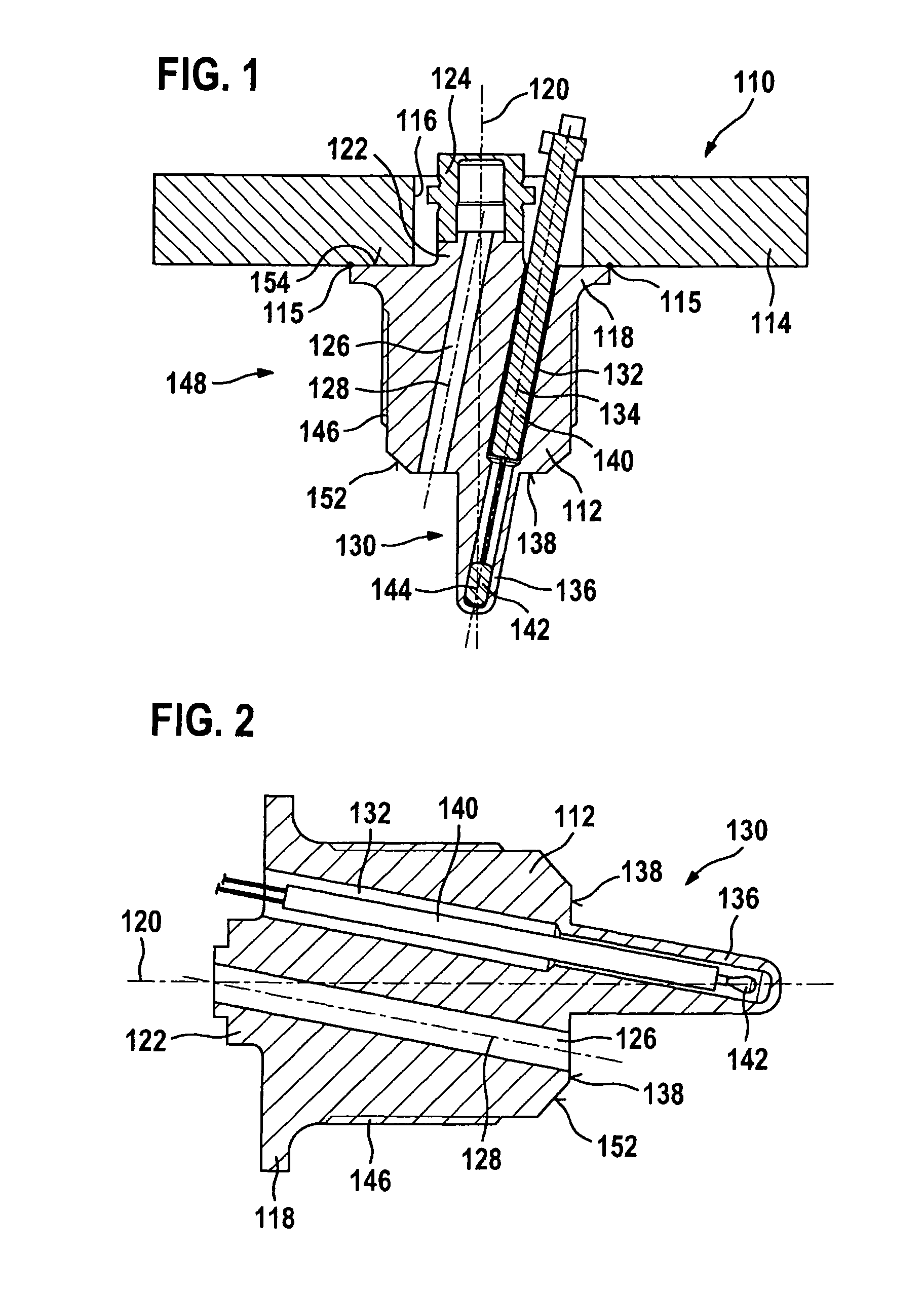
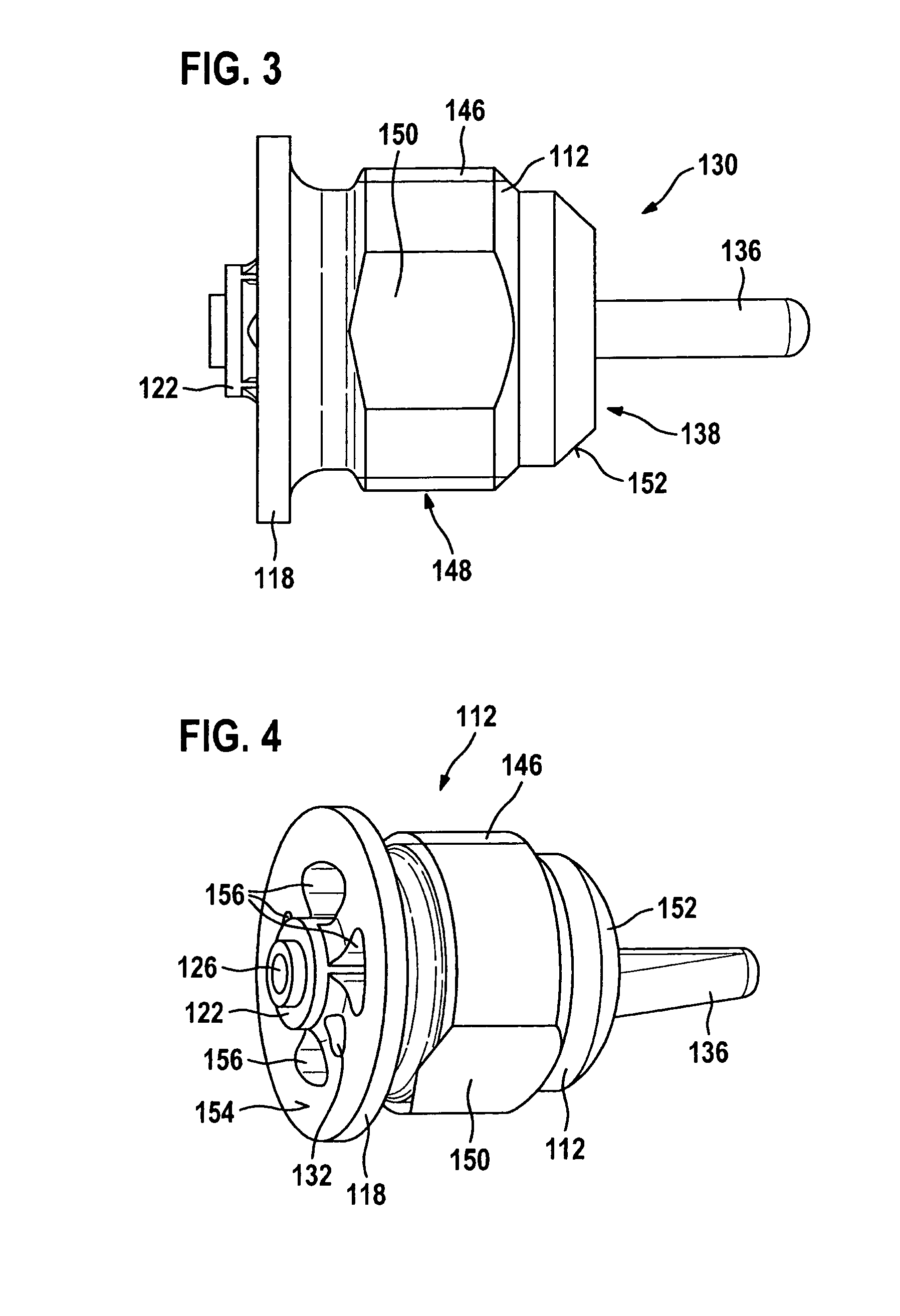
[0037]FIGS. 1 through 4 depict a first exemplifying embodiment of a sensor plug 110 according to the present invention. FIG. 1 is a sectioned depiction of sensor plug 110, FIG. 2 a sectioned depiction of a sensor body 112 of sensor plug 110, FIG. 3 a side view of sensor body 112, and FIG. 4 a perspective depiction of sensor body 112. These Figures will be described below in combination.

[0038]Sensor plug 110 according to FIG. 1 has, in addition to sensor body 112, a hexagon 114 having a central orifice 116. Sensor body 112 is joined to hexagon 114 by an intermaterial connection 115 (e.g. welding) in such a way that sensor body 112 is disposed concentrically with central orifice 116, and the upper side of sensor body 112 is accessible through central orifice 116. The intermaterial connections of the individual components are labeled in general in the Figures with the reference character 115. For the purpose of this intermaterial connection 115, sensor body 112 has on its upper end, fa...


PUM

PropertyMeasurementUnit
angleaaaaaaaaaa
angleaaaaaaaaaa
temperaturesaaaaaaaaaa

Abstract

A sensor plug for pressure and temperature measurement of a fluid medium includes a sensor body having a sensor body axis, as well as a pressure sensor disposed substantially concentrically on the sensor body axis. Also provided in the sensor body is a through orifice for connecting the pressure sensor to the fluid medium, and a temperature sensing element orifice having a temperature sensing element received therein. The temperature sensing element orifice has a temperature sensing element orifice axis that is inclined with respect to the sensor body axis in such a way that at its end pointing toward the fluid medium, it is inclined toward the sensor body axis.

Description

BACKGROUND OF THE INVENTION[0001]1. Field of the Invention[0002]The present invention relates to a sensor plug for pressure and temperature measurement, e.g., for fluid medium.[0003]2. Description of Related Art[0004]In various sectors of technology, different parameters of fluid media, i.e. of gases and / or liquids, must be measured simultaneously. In particular, a simultaneous measurement of pressure and temperature is necessary for many applications. Combined pressure and temperature measurement sensors, which are optimized for the relevant field of application, have been developed for this purpose.[0005]Combined pressure and temperature sensors for climate control systems are an important application example in this context. In climate control systems, the heat of vaporization of a coolant is usually used to cool air (or another medium to be cooled). The coolant is then compressed again, and thereby liquefied, in a compressor. Upon compression, the coolant heats up. This absorbed...

Claims


Application Information

Patent Timeline
Patent Type & Authority Patents(United States)
IPC IPC(8): G01K1/14G01K19/00B23P11/00
CPCG01D11/245G01D21/02G01L19/0092G01K1/08G01K13/02G01L19/14Y10T29/49826G01K2201/02
Inventor STOLL, OLIVERROESSER, CHRISTIANENGELHARDT, JOERG
Owner ROBERT BOSCH GMBH
Why Eureka
Try Eureka