Zoom lens and image pickup device

a pickup device and zoom lens technology, applied in the field of zoom lens and image pickup device, can solve the problems of hindering miniaturization and increasing the thickness of the second lens in the first lens group, and achieve the effects of wide angle of view, small size, and high variable power ratio

Active Publication Date: 2011-10-18
SONY CORP
View PDF8 Cites 6 Cited by
  • Summary
  • Abstract
  • Description
  • Claims
  • Application Information

AI Technical Summary

Benefits of technology

[0010]However, in the zoom lens described in Patent Document 2, a space between a constituent element forming an afocal system and having negative refractive power and a positive constituent element is filled with glass to decrease the inclination of light rays passing through the first lens group. Thus, the thickness of a second lens in the first lens group is increased, which hinders miniaturization.
[0011]It is accordingly desirable to overcome the above-described problems and achieve both a wider angle of view and a smaller size while having a high variable power ratio.
[0023]By making one of the front group and the rear group of the fifth lens group the movable group, the movable group has a small amount of travel in the direction perpendicular to the optical axis.
[0028]The zoom lens and the image pickup device according to the embodiments of the present invention can achieve both a wider angle of view and a smaller size while having a high variable power ratio.

Problems solved by technology

Thus, the thickness of a second lens in the first lens group is increased, which hinders miniaturization.

Method used


Image

  • Zoom lens and image pickup device
  • Zoom lens and image pickup device
  • Zoom lens and image pickup device

Examples


first embodiment

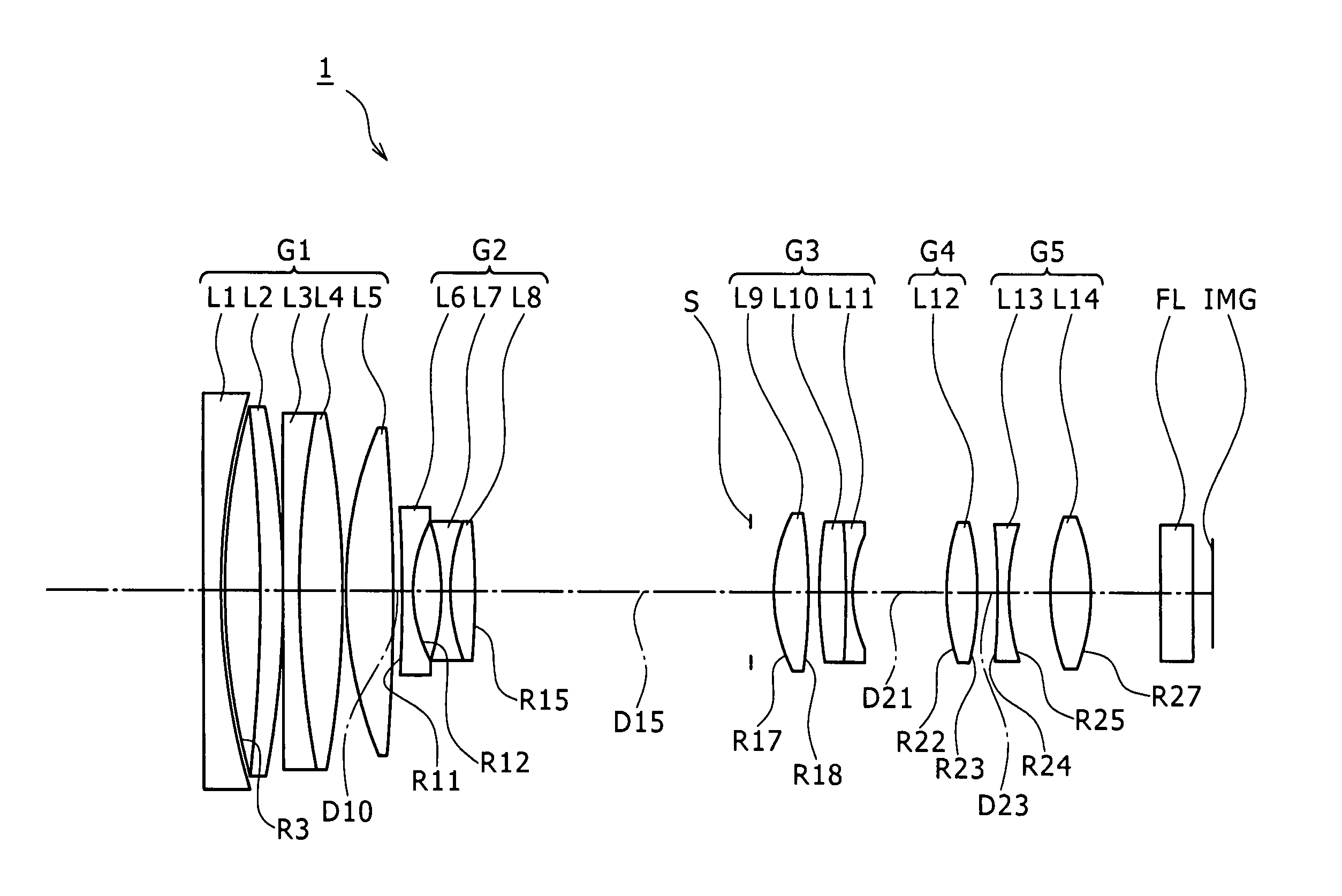
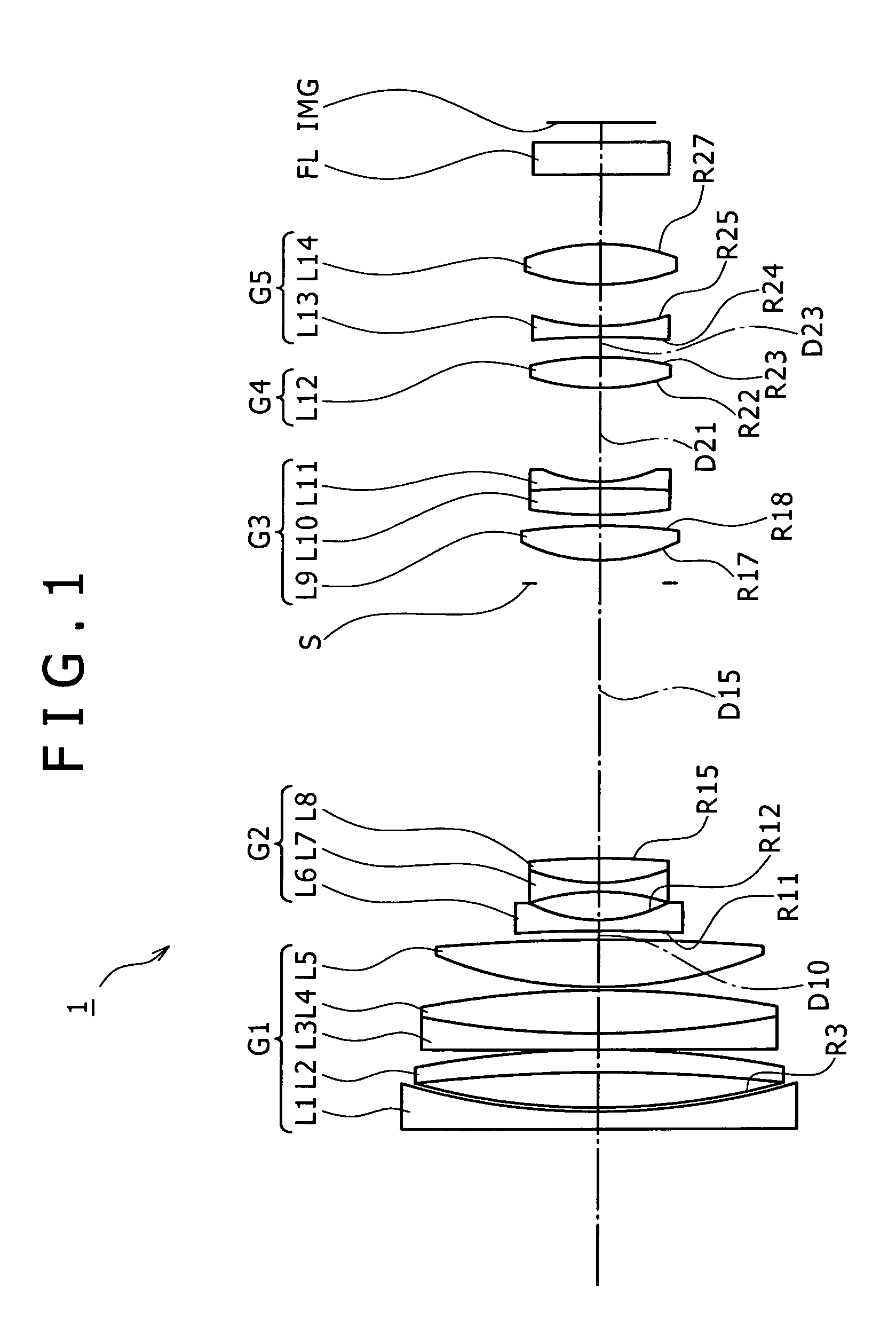
[0102]FIG. 1 shows a lens configuration of a zoom lens 1 in a first embodiment.

[0103]The variable power ratio of the zoom lens 1 is set at 8.74 times.

[0104]The zoom lens 1 is formed by arranging a first lens group G1 having positive refractive power, a second lens group G2 having negative refractive power, a third lens group G3 having positive refractive power, a fourth lens group G4 having positive refractive power, and a fifth lens group G5 having positive refractive power in order from an object side to an image side.

[0105]The first lens group G1 has a position fixed at all times. The second lens group G2 is made movable in a direction of an optical axis to vary power. The third lens group G3 has a position fixed at all times. The fourth lens group G4 is made movable in the direction of the optical axis to correct a focal position resulting from power variation and perform focusing.

[0106]The first lens group G1 is formed by arranging a lens L1 having a concave surface facing the ...

second embodiment

[0123]FIG. 5 shows a lens configuration of a zoom lens 2 according to a second embodiment.

[0124]The variable power ratio of the zoom lens 2 is set at 8.87 times.

[0125]The zoom lens 2 is formed by arranging a first lens group G1 having positive refractive power, a second lens group G2 having negative refractive power, a third lens group G3 having positive refractive power, a fourth lens group G4 having positive refractive power, and a fifth lens group G5 having positive refractive power in order from an object side to an image side.

[0126]The first lens group G1 has a position fixed at all times. The second lens group G2 is made movable in a direction of an optical axis to vary power. The third lens group G3 has a position fixed at all times. The fourth lens group G4 is made movable in the direction of the optical axis to correct a focal position resulting from power variation and perform focusing.

[0127]The first lens group G1 is formed by arranging a lens L1 having a concave surface ...

third embodiment

[0144]FIG. 9 shows a lens configuration of a zoom lens 3 according to a third embodiment.

[0145]The variable power ratio of the zoom lens 3 is set at 8.71 times.

[0146]The zoom lens 3 is formed by arranging a first lens group G1 having positive refractive power, a second lens group G2 having negative refractive power, a third lens group G3 having positive refractive power, a fourth lens group G4 having positive refractive power, and a fifth lens group G5 having positive refractive power in order from an object side to an image side.

[0147]The first lens group G1 has a position fixed at all times. The second lens group G2 is made movable in a direction of an optical axis to vary power. The third lens group G3 has a position fixed at all times. The fourth lens group G4 is made movable in the direction of the optical axis to correct a focal position resulting from power variation and perform focusing.

[0148]The first lens group G1 is formed by arranging a lens L1 having a concave surface f...


PUM


Abstract

Disclosed herein is a zoom lens including a first lens group, a second lens group, a third lens group, a fourth lens group, and a fifth lens group. The zoom lens satisfies following conditional expressions (1) and (2),0.03<H1′ / f1<0.3  (1)0.3<|f2| / √(fw·ft)<0.65  (2)where H1′ is an interval from a vertex of a surface nearest to the image side in the first lens group to a principal point on the image side of the first lens group (− denotes the object side, and + denotes the image side), f1 is focal length of the first lens group, f2 is focal length of the second lens group, fw is focal length of an entire lens system at a wide-angle end, and ft is the focal length of the entire lens system at a telephoto end.

Description

BACKGROUND OF THE INVENTION[0001]1. Field of the Invention[0002]The present invention relates to a zoom lens and an image pickup device, and particularly to a zoom lens and an image pickup device that achieve both a wider angle of view and a smaller size while having a high variable power ratio.[0003]2. Description of the Related Art[0004]Recently, image pickup devices such as digital still cameras, digital video cameras and the like have been miniaturized and spread widely for home use. In these image pickup devices, as image pickup elements are miniaturized, miniaturization of an entire lens system and a wide-angle zoom lens having a high variable power ratio and high performance are desired.[0005]It is generally known that a so-called inner focus type zoom lens used in video cameras and achieving focus by moving a lens group other than a first lens group disposed nearest to an object side facilitates miniaturization of an entire lens system and offers image forming performance su...

Claims


Application Information

Patent Timeline
Patent Type & Authority Patents(United States)
IPC IPC(8): G02B15/14
CPCG02B15/173G02B15/145129
Inventor MATSUNAGA, SHIGEHIKOTOYODA, KOJI
Owner SONY CORP
Why Eureka
Try Eureka