
Method and apparatus for adaptive reduced overhead transmit beamforming for wireless communication systems

a wireless communication system and overhead transmit beam technology, applied in electrical apparatus, digital transmission, duplex signal operation, etc., can solve the problems of large changes in the v matrix, inability to adapt to the effect of transmitting and inability to send the full csi as feedback

Inactive Publication Date: 2011-10-18
MEDIATEK INC
View PDF2 Cites 11 Cited by
  • Summary
  • Abstract
  • Description
  • Claims
  • Application Information

AI Technical Summary

Problems solved by technology

The data required to send the full CSI as feedback can be prohibitive because much dynamic range is required to represent a channel that has any significant fading.
The problem with this method is that small variations in the channel condition could lead to large changes to the V matrix.
Thus, this method may not be robust and suffers from sudden performance loss in both throughput and link stability.
Prior art limitations include feeding back an incomplete CSI to the transmitter; thereby limiting the type of beamforming processing that can be used, and, because it relies on the V matrix, it too may be sensitive to channel variations, as mentioned with the compressed method discussed above.

Method used


Image

  • Method and apparatus for adaptive reduced overhead transmit beamforming for wireless communication systems
  • Method and apparatus for adaptive reduced overhead transmit beamforming for wireless communication systems
  • Method and apparatus for adaptive reduced overhead transmit beamforming for wireless communication systems

Examples


Embodiment Construction

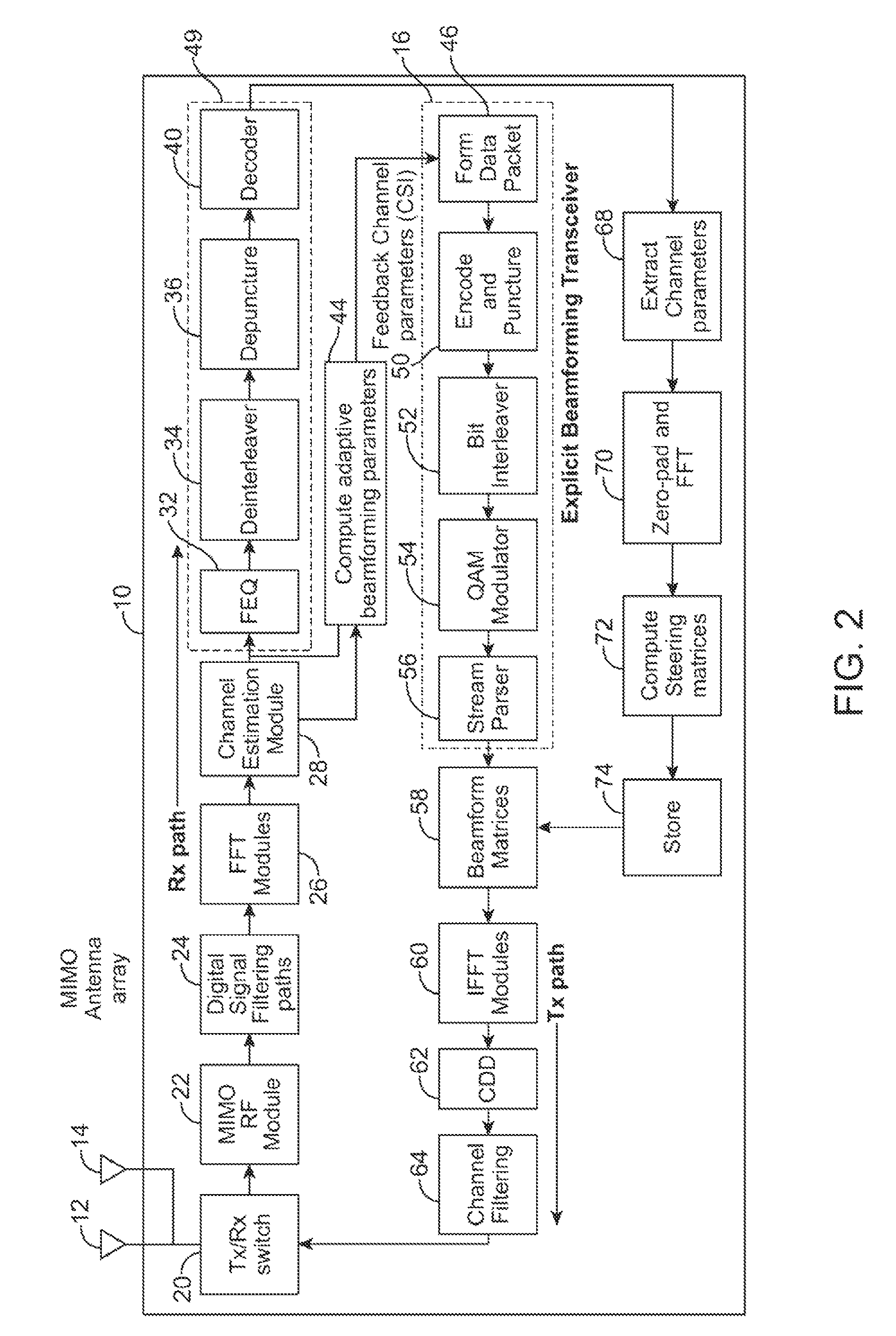
[0031]Referring now to FIG. 2, a multi input multi output (MIMO) transceiver 10 is shown to include a transmitter-receiver switch 20, a radio frequency (RF) module 22, a signal filtering module 24, a fast Fourier transform module (FFT) 26, a channel estimation module 28, an adaptive beamforming parameters module 44 and a decoding module 49, in accordance with an embodiment of the present invention. Also included in the MIMO transceiver 10 are an encoding module 16, a beamforming matrices module 58, an inverse fast Fourier transform (IFFT) module 60, a cyclic delay diversity (CDD) module 62 and a channel filtering module 64 as part of the transmission path, in accordance with an embodiment of the present invention. In addition, the MIMO transceiver 10 includes a channel parameters module 68, an FFT module 70, a steering matrices module 72 and a memory module 74.

[0032]The encoding module 16 includes a data forming module 46, an encode / puncture module 50, a bit interleaver 52, a modula...


PUM


Abstract

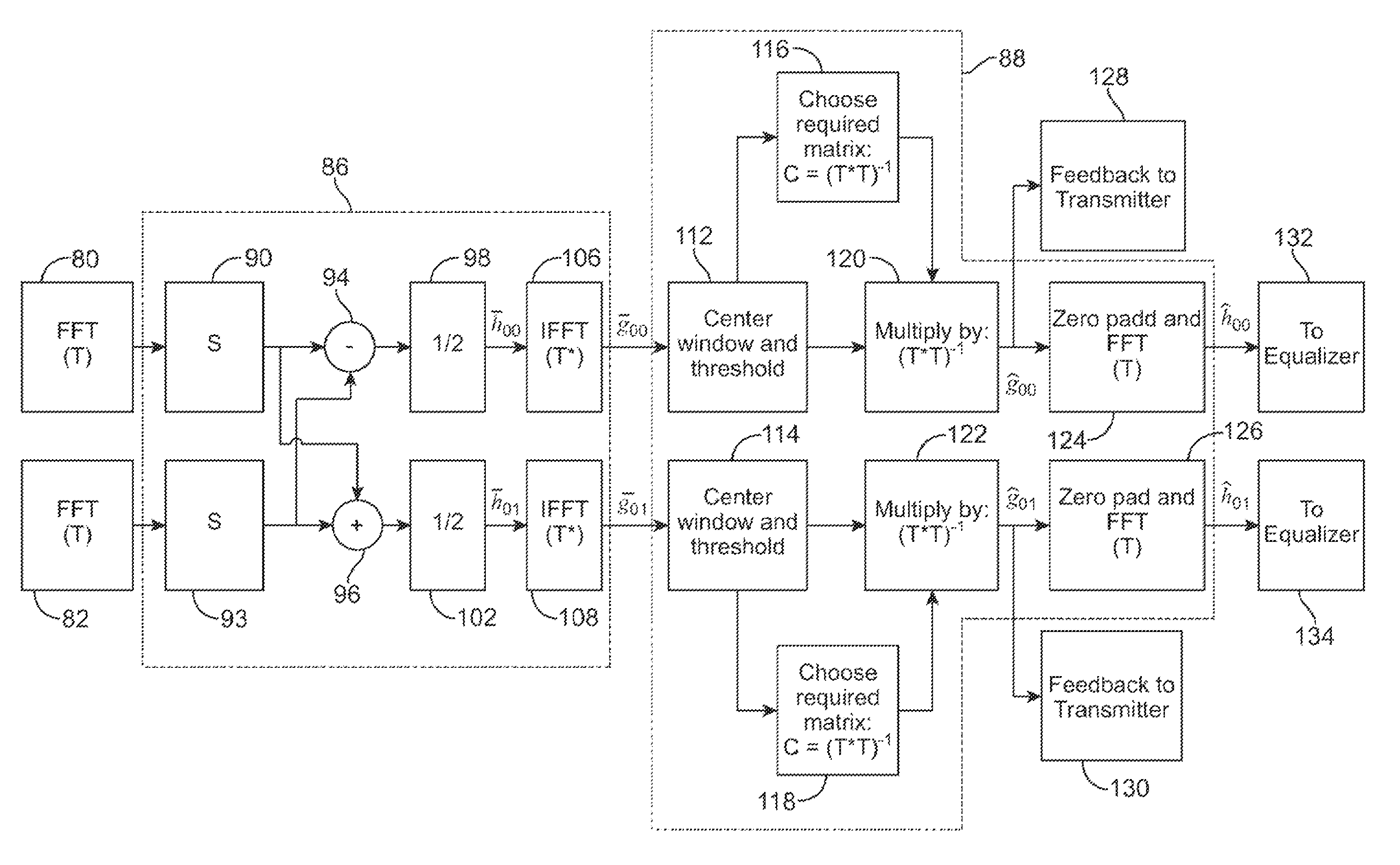
A multi input multi output (MIMO) transceiver having a channel estimation module being responsive to received samples including channel state information (CSI) and operative to generate time domain beamforming parameters, in accordance with an embodiment of the present invention. The multi input multi output (MIMO) transceiver further includes an adaptive beamforming parameters module coupled to receive said time domain beamforming parameters and operative to generate time domain adaptive beamforming parameters, said adaptive beamforming parameters module operative to process said time domain beamforming parameters to generate frequency domain adaptive beamforming parameters, a decoding module coupled to receive said frequency domain adaptive beamforming parameters and operative to generate data bits, a channel parameters module coupled to receive said data bits and operative to extract said time domain adaptive beamforming parameters, an encoding module coupled to receive said time domain adaptive beamforming parameters and operative to generate a data packet, said encoding module operative to encode said data packet to generate a modulated data stream, and a beamform matrices module coupled to receive said modulated data stream and operative to generate a beamformed data stream based on said frequency domain adaptive beamforming parameters, said MIMO transceiver operative to process said beamformed data stream to generate output signals and to transmit said output signals by forming beam patterns.

Description

CROSS REFERENCE TO PRIOR APPLICATIONS[0001]This application is a continuation-in-part application of my previous U.S. patent application Ser. No. 11 / 840,897, filed on Aug. 17, 2007, and entitled “METHOD AND APPARATUS FOR CALIBRATION FOR BEAMFORMING OF MULTI-INPUT-MULTI-OUTPUT (MIMO) ORTHOGONOL FREQUENCY DIVISION MULTIPLEXING (OFDM) TRANSCEIVERS”, the disclosure of which is incorporated herein by reference as though set forth in full.BACKGROUND OF THE INVENTION[0002]1. Field of the Invention[0003]The present invention relates generally to the field of wireless communication systems and particularly to a method and apparatus for adaptive transmit beamforming with reduced overhead in multi input multi output (MIMO) communication systems.[0004]2. Description of the Prior Art[0005]Communication systems can be categorized as conforming to either wired or wireless standards. Implementations can range from local wireless networks in the home, to the national and international cell phone net...

Claims


Application Information

Patent Timeline
Patent Type & Authority Patents(United States)
IPC IPC(8): H04L27/00
CPCH04B7/0413
Inventor PARE, JR., THOMAS EDWARD
Owner MEDIATEK INC
Learn More