
Method of controlling power states in a multimedia system

a multimedia system and power state technology, applied in the field of methods and systems for monitoring and controlling the power state in the multimedia system, can solve the problems of power state only partially power is much more complicated than in prior art systems, and the power state of each individual device cannot be monitored in such prior art systems

Inactive Publication Date: 2011-10-18
KONINK PHILIPS ELECTRONICS NV
View PDF4 Cites 4 Cited by
  • Summary
  • Abstract
  • Description
  • Claims
  • Application Information

AI Technical Summary

Benefits of technology

[0023]In one embodiment, the step of providing information to the receiver module and / or the transmitter module indicating the current power state of the multimedia source comprises transmitting data indicating the current power state of the multimedia source to the receiver module. In another embodiment, the step of providing information to the receiver module and / or the transmitter module indicating the current power state of the multimedia source is based on the signal activity at the transmitter module or the multimedia source, wherein the receiver module is adapted to automatically detect the signal activity and based thereon determined the current power state of the transmitter module. In that way, the modules can be informed in an effective way about the current power state of the power sources.

Problems solved by technology

The power state of each individual device cannot be monitored in such prior art systems, only the power state of the whole system.
Therefore, the power states can only partially be monitored, using the +5V and HPD mechanism.
In the newest / next generation of such multimedia systems where transmitter (TX) and receiver (RX) modules are required as intermediate objects to provide a connection between the source and the sink, where the modules are interfaced via HDMI, the power is much more complicated than in prior art systems.
Also, since the bandwidth required for the forward links for passing audio / video data from the source to the sink is much higher than the bandwidth required for the backward link from the sink to the source, the power behavior of the system becomes more complicated since the modules most likely have their own power states and may not have a complete transparent view on the peer device, as would be the case when a standard HDMI cable would be used.

Method used


Image

  • Method of controlling power states in a multimedia system
  • Method of controlling power states in a multimedia system
  • Method of controlling power states in a multimedia system

Examples


Embodiment Construction

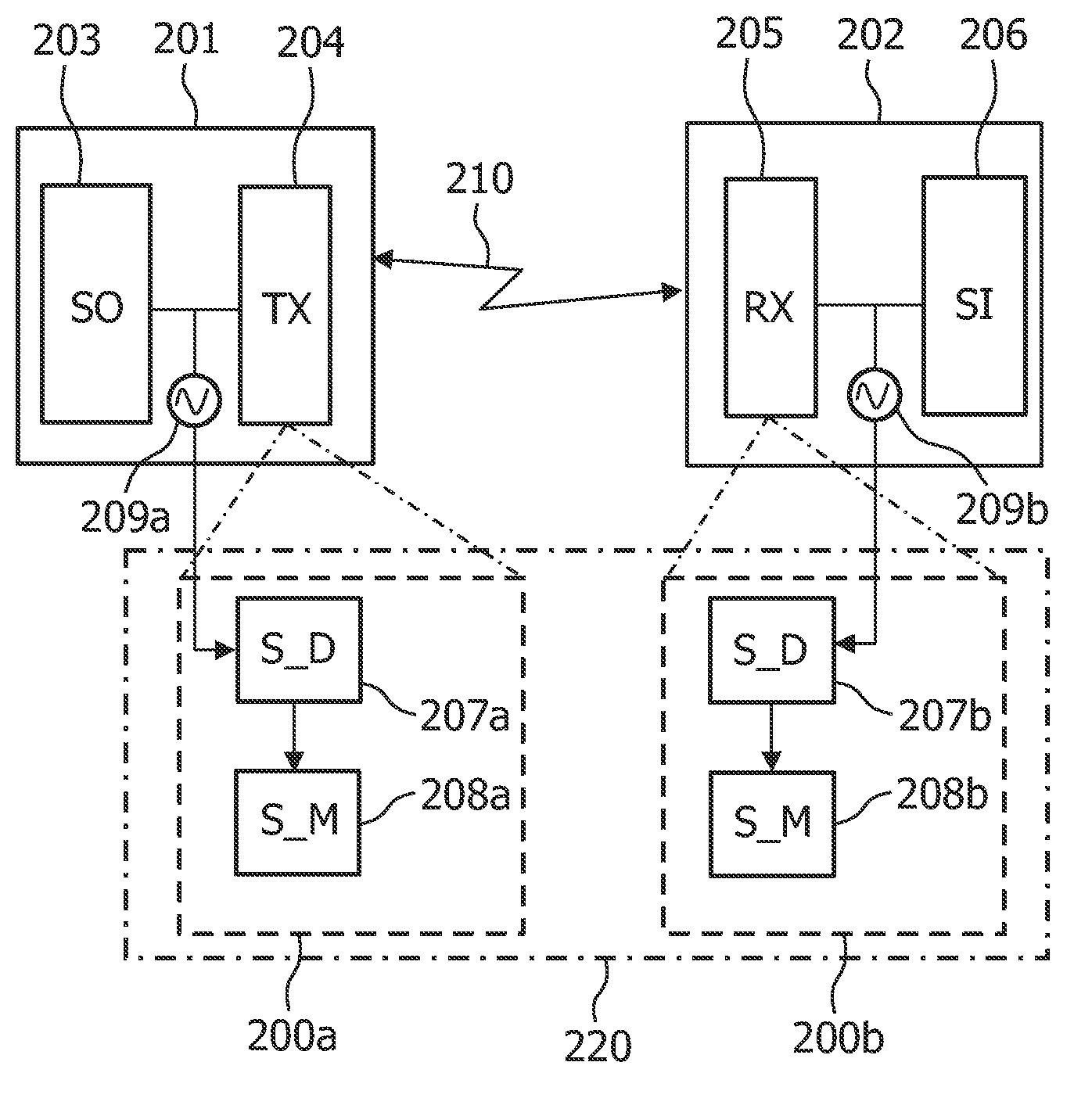
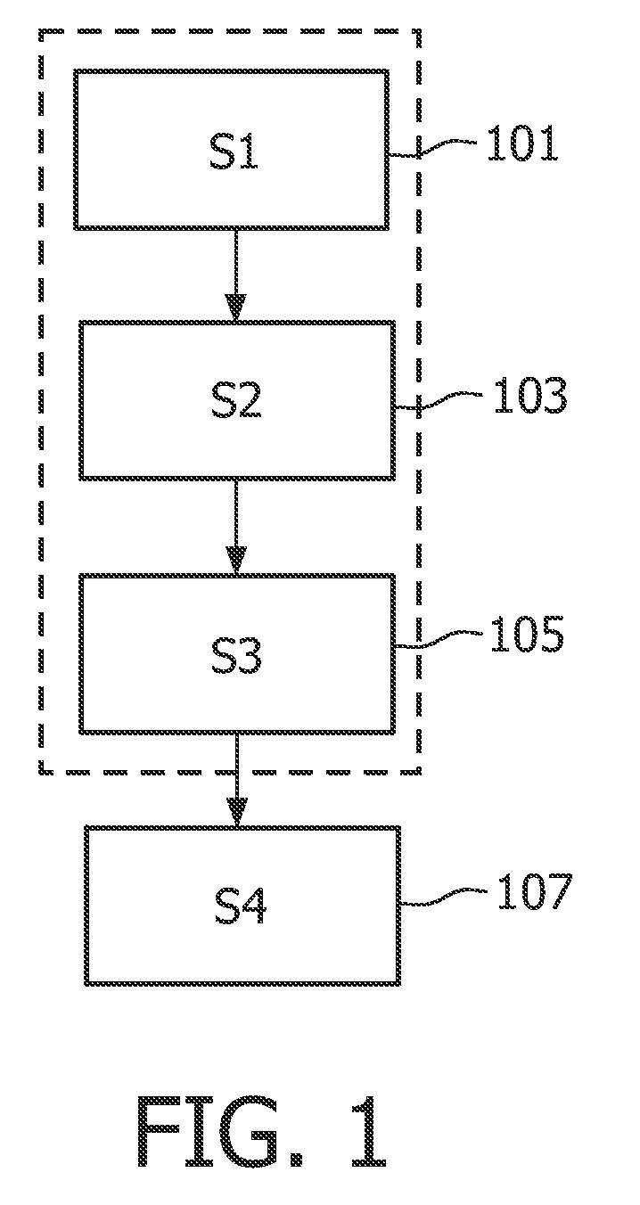
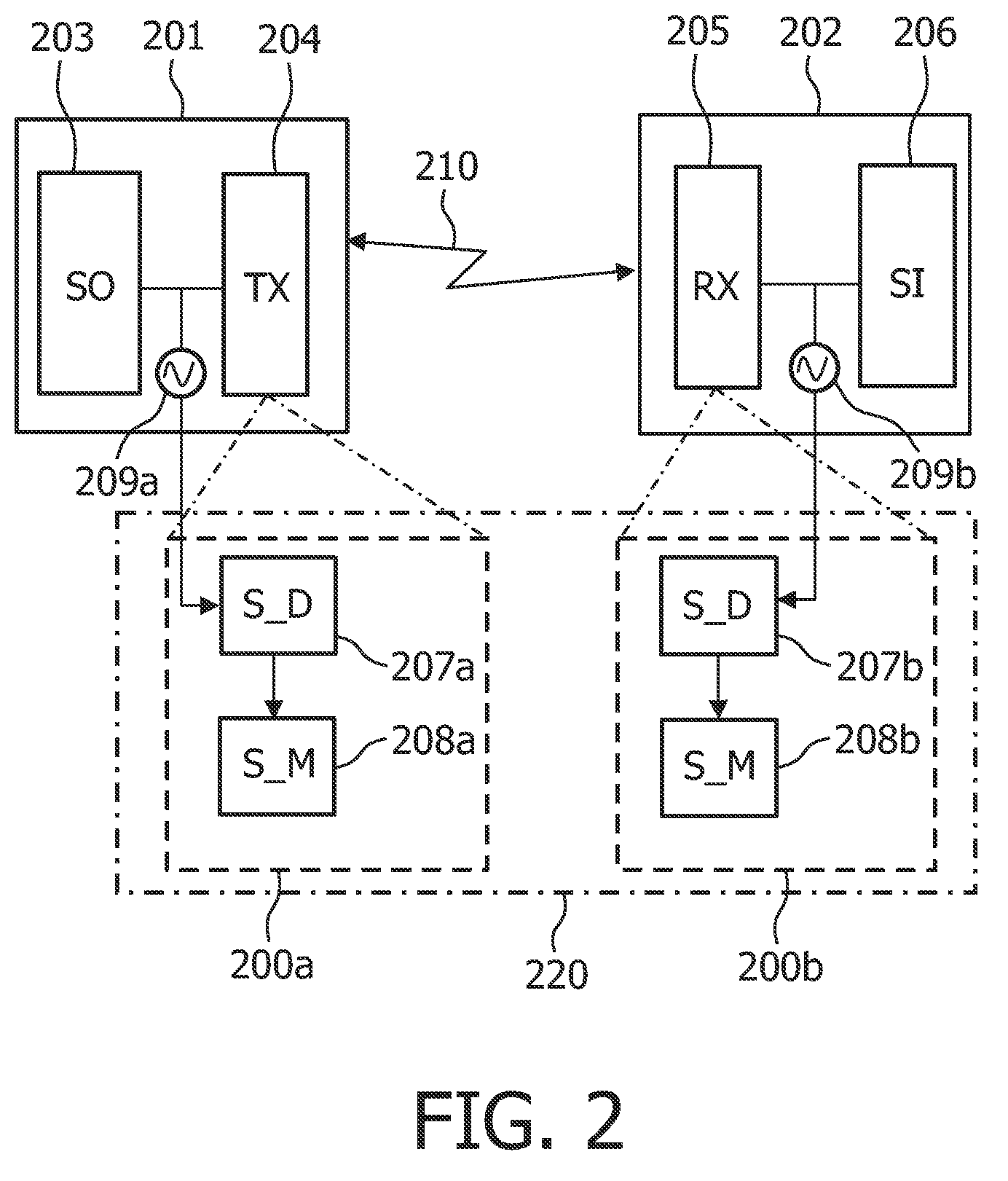
[0059]FIG. 1 shows a method according to the present invention of controlling the power states in a multimedia system comprising a multimedia connector box including a multimedia source interconnected to a transmitter module (TX), and a multimedia device including a receiver module (RX) interconnected to a multimedia sink, wherein the TX and the RX are interfaced via multimedia interfacing means, such as optical or wirelessly based High-Definition-Multimedia-Interface (HDMI) connection. Such a multimedia system can comprise compatible digital audio / video source, such as a set-top box, DVD player, and A / V receiver and a compatible digital audio and / or video monitor, such as a digital television (DTV).

[0060]In a preferred embodiment, the TX and RX are powered through the source and the sink, but an external AC / DC could just as well be used as a power source.

[0061]Referring to the flow chart in FIG. 1, steps (S1)-(S4) apply to the connector box side, and step (S5) to the multimedia dev...


PUM


Abstract

This invention relates to controlling the power states in a multimedia system comprising a multimedia connector box including a multimedia source interconnected to a transmitter module, and a multimedia device including a receiver module interconnected to a multimedia sink, wherein the transmitter and the receiver modules interface the multimedia connector box and the multimedia device via multimedia interfacing means. A signal detector detects the signal activity between the power sources of the multimedia system for determining the current power state of the power sources, and a power switching mechanism adapts the power states of the transmitter and receiving modules to the power states of the power sources.

Description

[0001]This application is a 371 of PCT / IB2006 / 052866, filed Aug. 18, 2006.FIELD OF THE INVENTION[0002]The present invention relates to a method and a system for monitoring and controlling the power states in a multimedia system comprising a multimedia connector box including a multimedia source interconnected to a transmitter module, and a multimedia device including a receiver module interconnected to a multimedia sink, wherein the transmitter and the receiver modules interface the multimedia connector box and the multimedia device via multimedia interfacing means. The present invention further relates to computer readable media for storing instructions for enabling a processing unit to execute the method. The present invention further relates to a communication protocol arranged to implement a power control of the system. The present invention further relates to a mechanism adapted to be implemented in the multimedia system for controlling the power states in the multimedia system...

Claims


Application Information

Patent Timeline
Patent Type & Authority Patents(United States)
IPC IPC(8): H04N7/16H04N5/00
CPCH04N7/163H04N21/43632H04N21/44209H04N21/4424H04N21/44245H04N21/443H04N21/4436
Inventor VERGOOSSEN, THEODORUS ANNA PETER GERTRUDISDRIESEN, BAS
Owner KONINK PHILIPS ELECTRONICS NV
Learn More