
Wiper assembly having side-saddle coupler

a technology of windshield wipers and couplers, which is applied in the field of windshield wiper assemblies, can solve the problems of reducing the effectiveness of the windshield wiper assembly to clean the windshield, affecting the overall aesthetics of a particular vehicle, and reducing the drag and wind lift, so as to maximize the downward force of the windshield wiper assembly and maximize the downward force. the effect of the air current flowing

Active Publication Date: 2011-10-25
TRICO PROD CORP
View PDF53 Cites 9 Cited by
  • Summary
  • Abstract
  • Description
  • Claims
  • Application Information

AI Technical Summary

Benefits of technology

"The present invention is a wiper assembly that improves wind lift resistance, maximizes downward force, and reduces lateral movement and chatter during operation. It includes a coupler with a side-saddle that releasably connects to a wiper arm attachment member. The coupler efficiently utilizes the air current flowing over the assembly to maximize downward force applied to a wiper assembly. The side-saddle coupler prevents excess lateral movement of the wiper assembly relative to the wiper arm, reducing the likelihood of chatter during operational movement across the surface to be wiped."

Problems solved by technology

However, the increased vertical profile of the wiper assembly elevates the proximity of the wiper arm relative to the windshield, which increases drag and wind lift.
During wind lift, the wiper assembly lifts from the windshield of the vehicle, which can decrease the effectiveness of the windshield wiper assembly to clean the windshield.
Additionally, the increased vertical profile of the wiper assembly and wiper arm may have an adverse effect on the overall aesthetics of a particular vehicle.
As a result of the functional and aesthetic issues surrounding vertical-mount wiper assemblies, airfoils of various designs have been employed to reduce wind lift and streamline appearance.
However, side-mount wiper assemblies known in the art generally do not provide the lateral stability offered by the vertical-mount wiper assemblies.

Method used


Image

  • Wiper assembly having side-saddle coupler
  • Wiper assembly having side-saddle coupler
  • Wiper assembly having side-saddle coupler

Examples


Embodiment Construction

)

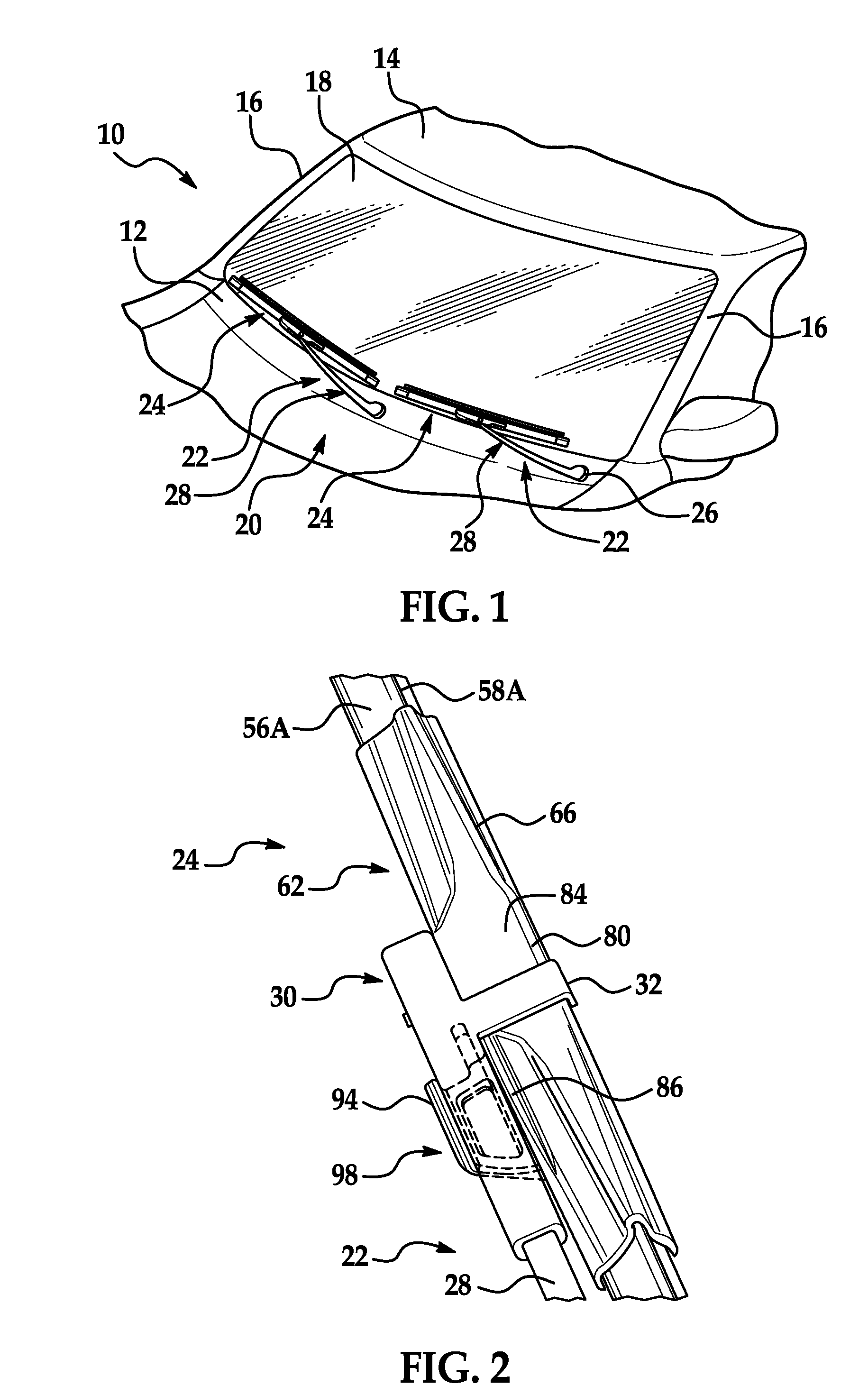
[0022]Referring now to the Figures, where like numerals are used to designate like structure, a portion of a vehicle is schematically illustrated at 10 in FIG. 1. The vehicle includes a cowl 12, a roof 14, and a pair of laterally spaced front or “A” pillars 16 extending between the roof 14 and the cowl 12. The A-pillars, roof, and cowl cooperate to define a generally rectangular opening which supports a curved or “swept back” glass windshield 18.

[0023]A wiper system is generally indicated at 20 in FIG. 1 and is employed to clean the glass windshield 18. The wiper system 20 includes wiper arms, generally indicated at 22 and wiper assemblies of the present invention, generally indicated at 24, which correspond to the driver and passenger side of the vehicle 10. An electrical motor (not shown but generally known in the art) is employed to power the wiper system 20 and a drive linkage assembly (not shown but generally known in the art) may be employed to direct the wiper assemblies 24,...


PUM


Abstract

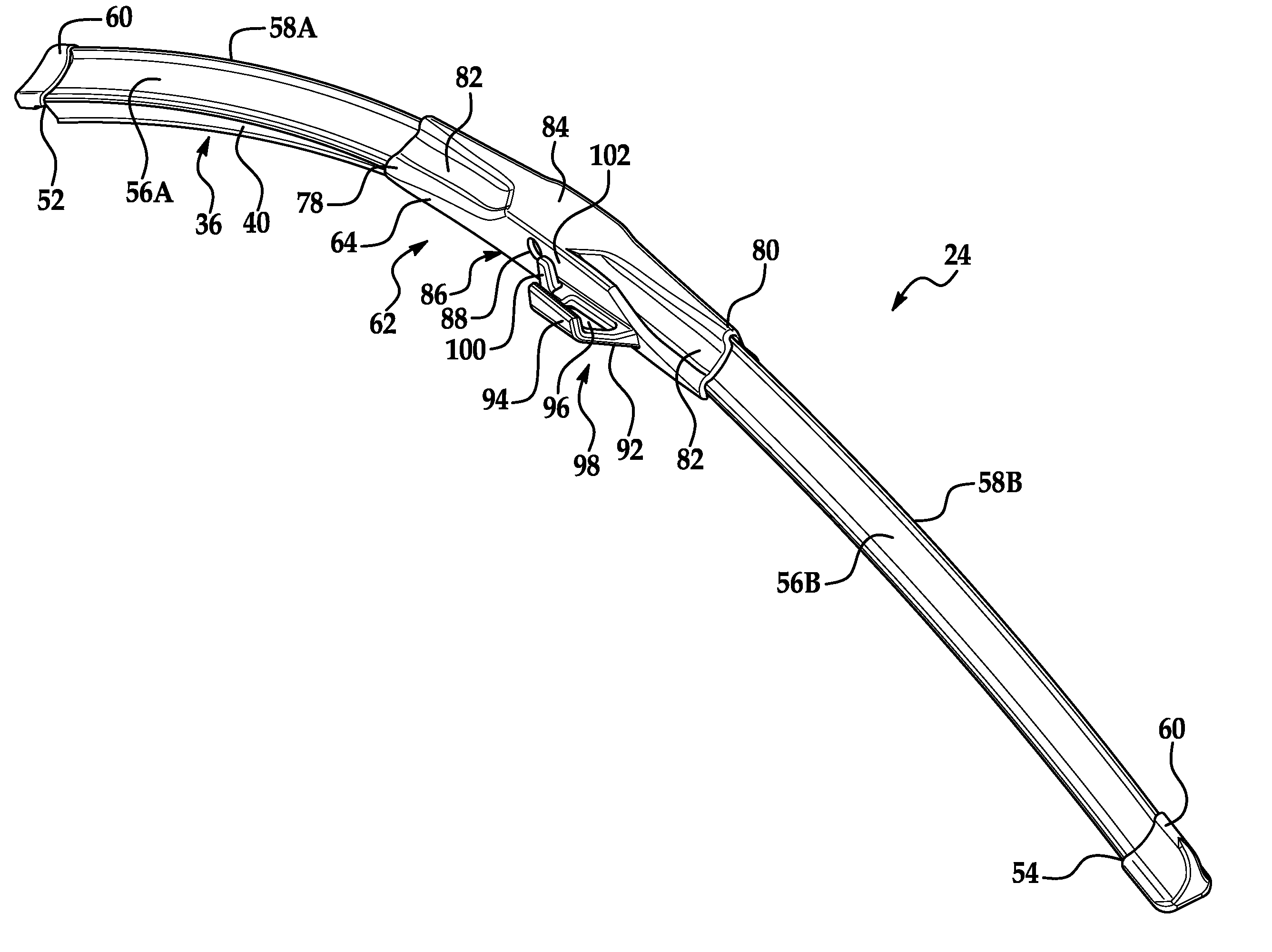
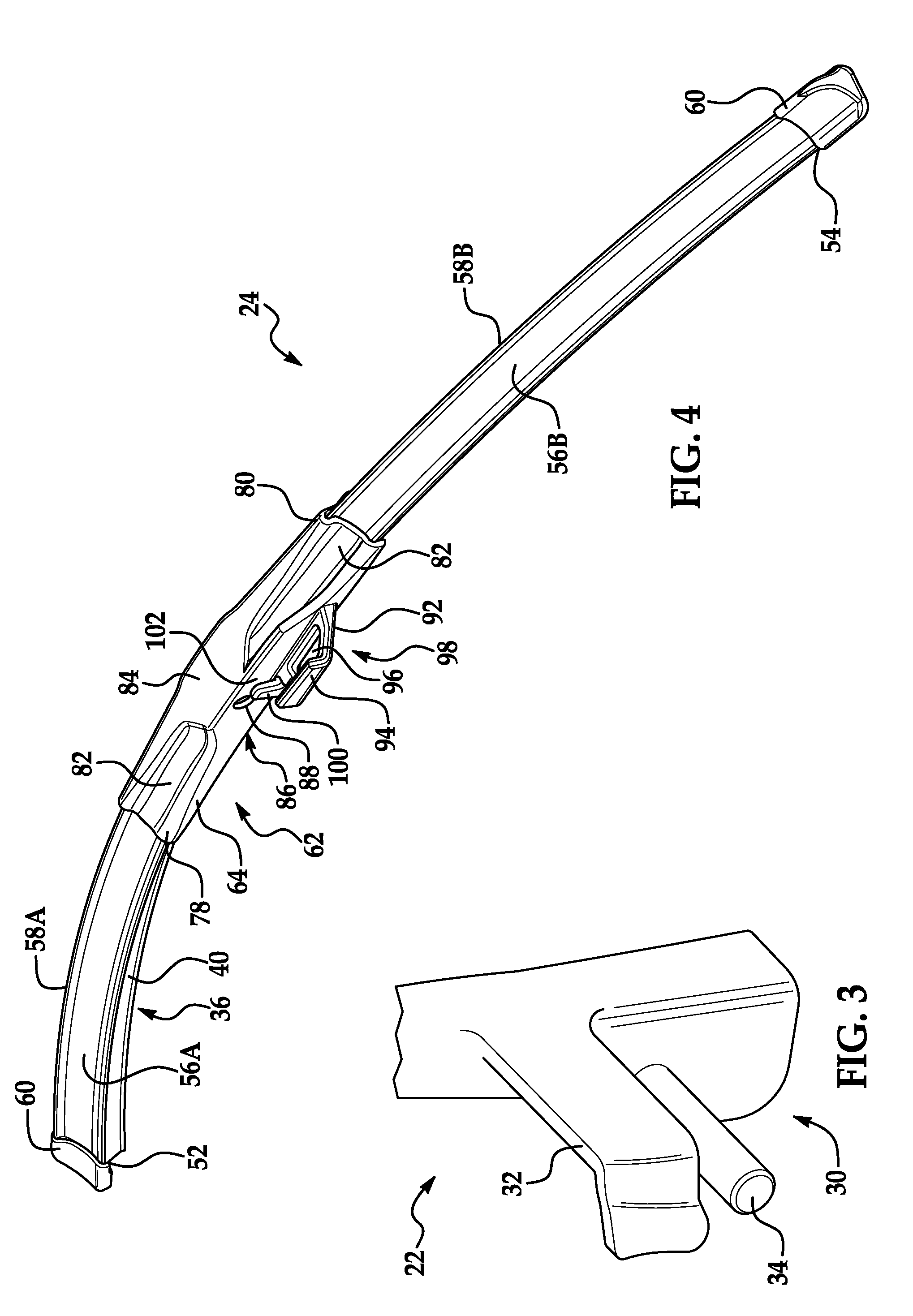
A wiper assembly for use in connection with a wiper arm attachment member having a transversely extending pin and bent tab. The wiper assembly includes a wiping element and a superstructure having first and second longitudinal ends. The wiper assembly further includes first and second airfoils attached to the superstructure between an intermediate position and the longitudinal ends. The wiper assembly further includes a coupler attached to the superstructure and disposed between the first and second airfoils. The coupler includes first and second sidewalls, a deck that extends from the first sidewall and a rail that extends from the deck. The deck and rail of the wiper assembly cooperate to define a side-saddle that facilitates low-profile attachment to a wiper arm attachment member for reducing the likelihood of wind lift and lateral movement between the wiper arm attachment member and the wiper assembly.

Description

CROSS REFERENCE TO RELATED APPLICATIONS[0001]This application claims the benefit of U.S. provisional patent application entitled “Wiper Assembly Having Side-Saddle Coupler,” having Ser. No. 60 / 921,986, and filed on Apr. 5, 2007.BACKGROUND OF THE INVENTION[0002]1. Field of the Invention[0003]The present invention relates, generally, to windshield wiper assemblies. More specifically, to a wiper assembly having a side-saddle coupler for use in connecting the wiper assembly to the wiper arm of a vehicle.[0004]2. Description of the Related Art[0005]Windshield wiper systems known in the related art typically include a wiper assembly having a wiping element that contacts the surface to be wiped and a wiper arm that imparts a reciprocating movement to the wiper assembly across the surface to be wiped. The wiper assembly is releasably connected to the wiper arm through a coupler. Conventional windshield wiper assemblies known in the related art generally consist of two types, commonly referr...

Claims


Application Information

Patent Timeline
Patent Type & Authority Patents(United States)
IPC IPC(8): B60S1/38
CPCB60S1/3856B60S1/4077B60S1/407B60S1/381B60S1/3875B60S1/3863B60S1/02B60S1/38B60S1/3806B60S1/3848B60S1/40
Inventor MOLL, KYLELOZANO, ROLANDO
Owner TRICO PROD CORP
Learn More