
Tool holder dampening system

a tool holder and dampening technology, which is applied in the direction of attachable milling devices, turning machine accessories, manufacturing tools, etc., can solve the problems that the contact between metals, though preferable, cannot be achieved, and achieve the effect of facilitating the complete insertion of the tool holder into the spindle, eliminating harmonic resonance, and maintaining the cleanliness of the spindle/tool holder combination

Active Publication Date: 2011-10-25
COOK HAROLD D
View PDF25 Cites 5 Cited by
  • Summary
  • Abstract
  • Description
  • Claims
  • Application Information

AI Technical Summary

Benefits of technology

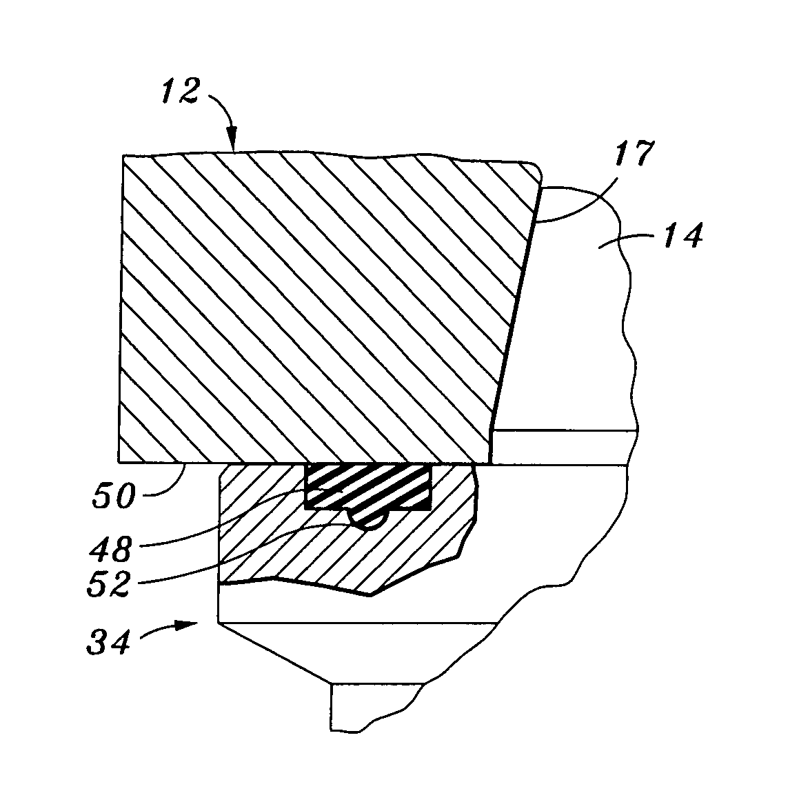
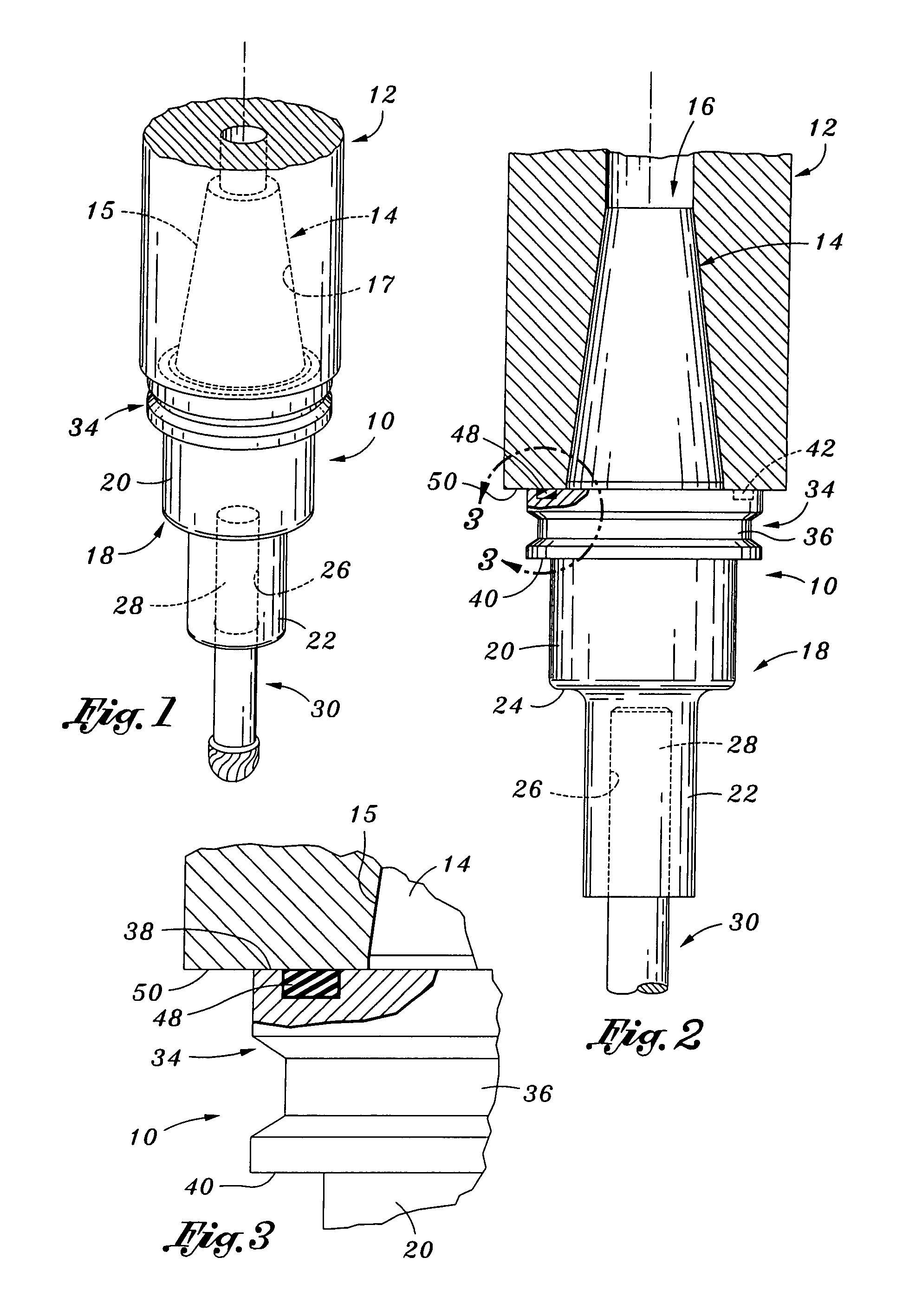
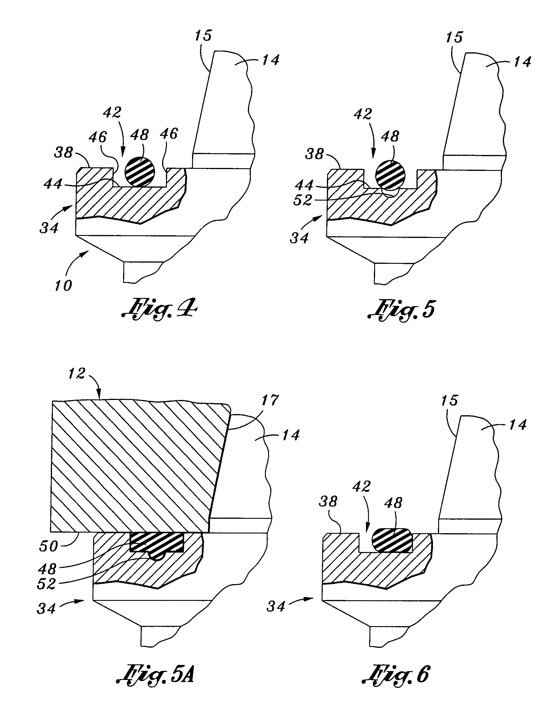
"The present invention provides a tool holder for use in a milling machine that includes a conically tapered shank portion that is inserted into a complimentary recess within the spindle. The tool holder also includes a cutting tool mounting portion with an aperture for receiving the shank portion of a cutting tool. A circularly configured flange portion extends radially outward relative to the shank and mounting portions and includes a V-shaped slot or recess for accommodating an automated tool holder changer. An annular, ring-like dampening member is disposed within a complimentary groove or channel in the flange portion and is compressed between the flange portion and the spindle to eliminate harmonic resonance and create a seal to prevent debris or contaminants from getting between the shank portion of the tool holder and the recess of the spindle. The dampening member prevents excessive radial displacement of the tool holder when used in extremely high speed milling applications."

Problems solved by technology

However, such metal-to-metal contact, though preferable, need not necessarily be achieved.

Method used


Image

  • Tool holder dampening system
  • Tool holder dampening system
  • Tool holder dampening system

Examples


second embodiment

[0038]Referring now to FIG. 7, there is shown a tool holder 10a constructed in accordance with the present invention. The tool holder 10a is structurally identical to the above-described tool holder 10, with the distinction between the tool holders 10, 10a lying in the inclusion of additional dampening members 54 within the shank portion 14a of the tool holder 10a. More particularly, the tool holder 10a is preferably formed to include a plurality of continuous channels or grooves 56 which are formed in the tapered outer surface 15a of the shank portion 14a in spaced, generally parallel relation to each other and to the flange portion 34a. Disposed within each of the grooves 56 is a respective one of the dampening members 54. As will be recognized by those of ordinary skill in the art, due to the tapered configuration of the shank portion 14a, the circumference of the groove 56 disposed closest to the flange portion 34a exceeds the circumference of the groove 56 disposed furthest fro...

third embodiment

[0047]Referring now to FIG. 10, there is shown a tool holder 10b which is constructed in accordance with the present invention and is also adapted for use in the rotating spindle 12. The tool holder 10b comprises a cutting tool mounting portion 18b. The mounting portion 18b itself defines a cylindrically configured upper section 20b, and a cylindrically configured lower section 22b. The lower section 22b extends axially from the upper section 20b, and has an outer diameter which is less than that of the upper section 20b such that an annular shoulder 24b is defined between the upper and lower sections 20b, 22b. Extending axially within the lower section 22b is a central aperture 26b which is adapted to receive the shank portion 28 of the cutting tool 30. It will be recognized that the mounting portion 18b may be of uniform diameter rather than including the differently sized upper and lower sections 20b, 22b described above and shown in FIG. 10.

[0048]The tool holder 10b further comp...


PUM

PropertyMeasurementUnit
lengthsaaaaaaaaaa
lengthaaaaaaaaaa
lengthaaaaaaaaaa

Abstract

A tool holder for use in a rotating spindle of a milling machine. The tool holder comprises a conically tapered shank portion for insertion into the spindle and a cutting tool mounting portion. Disposed between the shank and mounting portions is a flange portion. The flange portion includes a continuous channel formed therein which circumvents the shank portion and is adapted to accommodate a dampening member. The dampening member is compressable between the flange portion and the spindle when the tool holder is inserted into the spindle, and is adapted to eliminate harmonic resonance attributable to the use of the tool holder with a cutting tool.

Description

CROSS-REFERENCE TO RELATED APPLICATIONS[0001]Not ApplicableSTATEMENT RE: FEDERALLY SPONSORED RESEARCH / DEVELOPMENT[0002]Not ApplicableBACKGROUND OF THE INVENTION[0003]1. Field of the Invention[0004]The present invention relates generally to rotary cutting machines such as milling machines, and more particularly to a vibration-dampened spindle and tool holder assembly which is adapted to eliminate the harmonic resonance which typically occurs during the use of cutting tools in high speed milling applications.[0005]2. Description of the Prior Art[0006]As is well known, various tool holders have been utilized in the prior art which interface with a rotating spindle of a machine such as a milling or boring machine to securely interface a cutting tool to the machine during the cutting of a work piece. A rotary cutting machine typically includes a motor-rotated spindle to which a tool holder is attached, the tool holder being configured to accommodate a shank portion of a cutting tool whic...

Claims


Application Information

Patent Timeline
Patent Type & Authority Patents(United States)
IPC IPC(8): B23Q3/12
CPCB23B31/006B23Q11/0032B23B2226/33B23B2250/16B23B2260/114Y10T409/303752Y10T409/304312Y10T408/76Y10T409/30952
Inventor COOK, HAROLD D.
Owner COOK HAROLD D
Learn More