
Ring stent

a ring stent and stent technology, applied in the field of stents, can solve the problems of not having good dimensional stability, difficult sealing of stent grafts, and stents may be covered or uncovered, so as to achieve good sealing, dimensional stability, and dimensional stability. the effect of stability

Active Publication Date: 2011-10-25
COOK MEDICAL TECH LLC
View PDF16 Cites 61 Cited by
  • Summary
  • Abstract
  • Description
  • Claims
  • Application Information

AI Technical Summary

Benefits of technology

[0006]It is the object of this invention to provide a self expanding stent which has good dimensional stability.
[0009]Alternatively each zig zag portion is formed by two struts with a bend, a circumferential portion and another bend between adjacent struts. In this arrangement the circumferential portion forms part of the respective ring which makes the attachment of the ring to a portion of graft material, as discussed below, more secure.
[0013]Preferably the at least one ring is a first ring and adjacent alternate bends of the zig zag portion and a second ring is spaced apart from the first ring and adjacent an opposite bend of the zig zag portion and there are at least two turns of wire in the second ring and a terminal end of the wire in the second ring is provided with a loop so that the stent does not present a pointed end of wire which could damage a vessel.
[0022]A stent according to this invention may be used at the ends of legs or arms of stent grafts to give dimensional stability where such arms or legs engage against the wall of a vessel. The stent can also be used as a short extension affixed to and extending from a fenestration in a stent graft to provide a good sealing and dimensionally stable surface for an extension arm from the fenestrated stent graft.

Problems solved by technology

Such stents may be covered or uncovered.
These stents do not have good dimensional stability because when formed into a cylindrical stent, unless constrained, their diameter is not fixed.
This means that in some situations, a stent may put more outwardly radial pressure on a vessel than is desirable or it may not be easy to seal a stent graft within such a cylindrical stent.

Method used


Image

  • Ring stent
  • Ring stent
  • Ring stent

Examples


Embodiment Construction

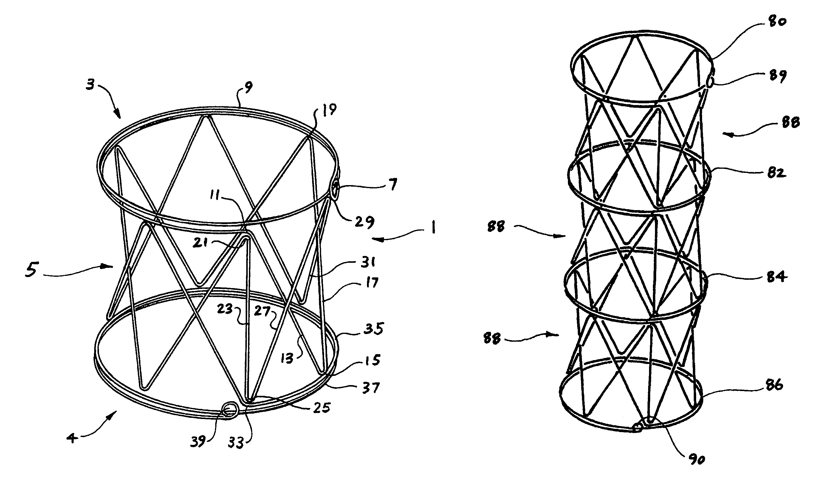
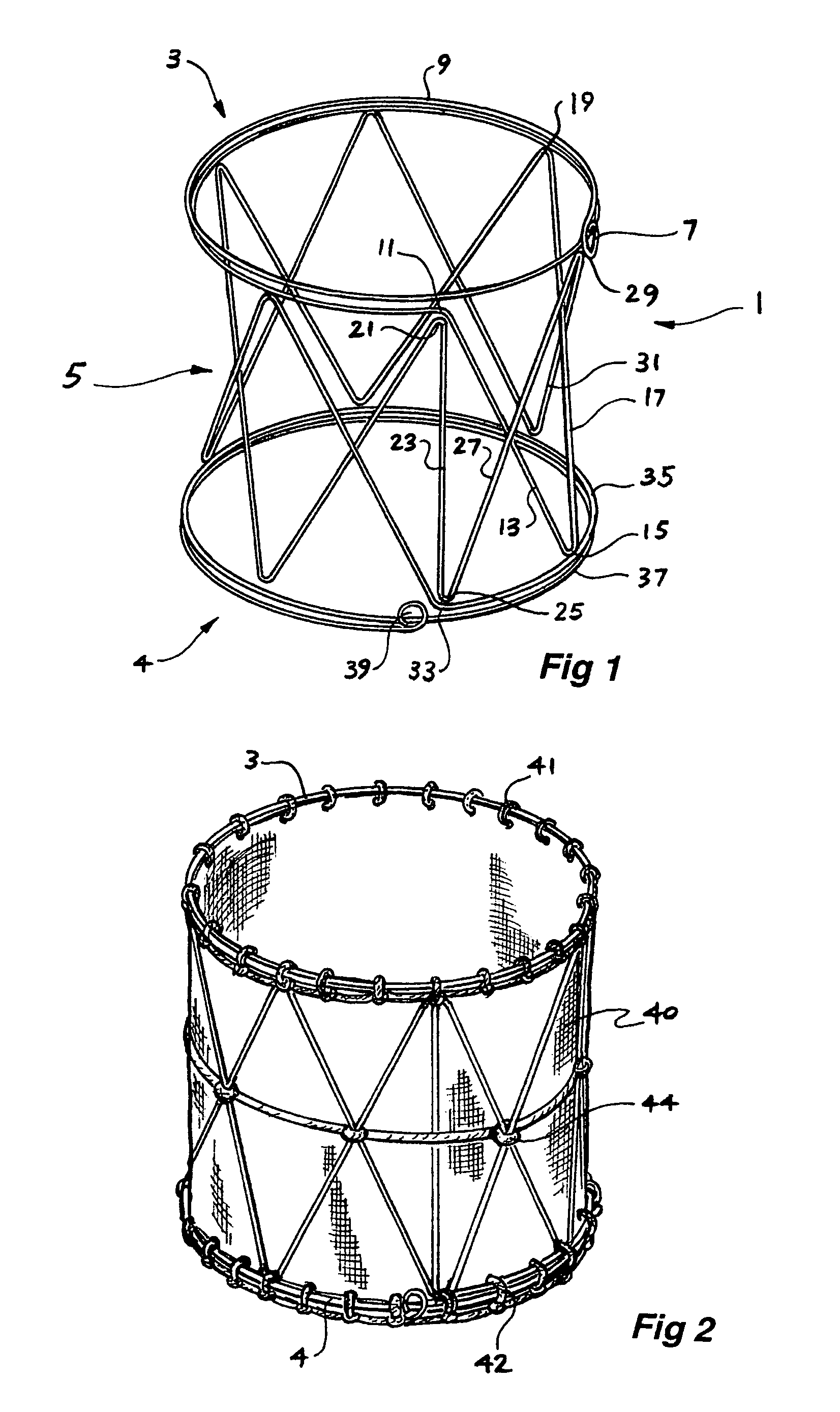
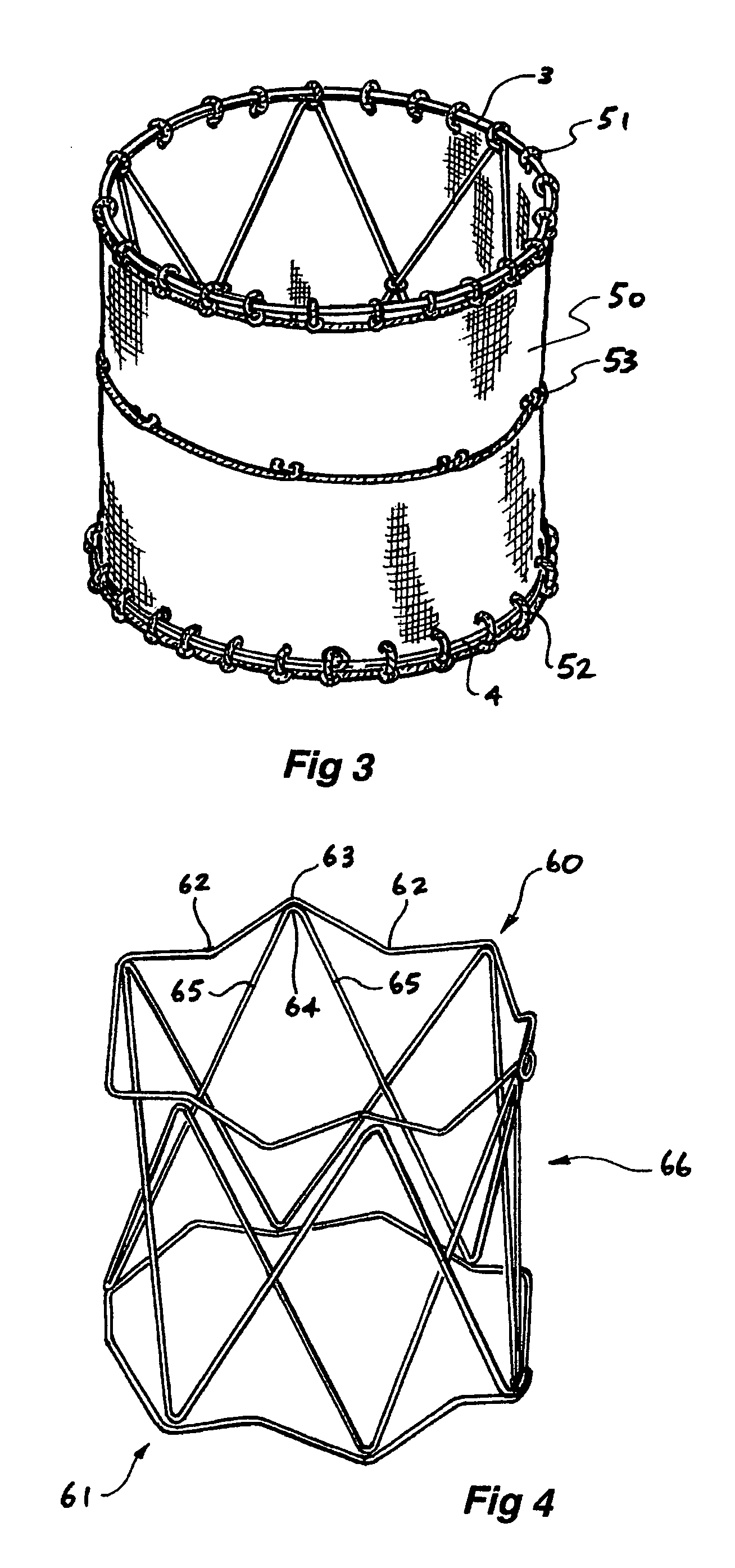
[0074]Now looking more closely at the drawings and in particular FIG. 1, it will be seen that the stent 1 according to one embodiment of this invention comprises a first resilient ring assembly 3 and a second resilient ring assembly 4 spaced (preferably parallel) to and axially away from the first ring assembly 3 and a number of zig zag struts 5 between the first resilient ring assembly 3 and the second resilient ring assembly 4. The first and second resilient ring assemblies and the struts comprise a metallic wire.

[0075]Although metal or metal alloy materials are preferred other resilient materials such as polymers, carbon fibres and other biocompatible materials are also contemplated.

[0076]The first ring assembly 3 commences at a loop 7 of the wire and is formed from two circles or turns of wire 9 and then at 11 there is a bend and the wire is angled in a first strut 13 extending to a bend 15 adjacent the second ring assembly 4 and then a further angled strut 17 to a bend 19 adjac...


PUM


Abstract

A stent arrangement which has at least a first ring (3) and zig zag struts (5) extending axially from the periphery of the ring. There can be first and second rings (3, 4) axially spaced apart and defining substantially parallel planes and a plurality of zig zag portions (5) between the first and second ring portions around the periphery thereof. The stent can be formed from a single wire or laser cut from a cannula and can be covered or uncovered.

Description

CROSS-REFERENCE TO RELATED APPLICATIONS[0001]This application claims priority of provisional application Ser. No. 60 / 510,242 filed Oct. 10, 2003.TECHNICAL FIELD[0002]This invention relates to a medical device and in particular to a stent for endovascular and endoluminal vessel repair and support.BACKGROUND OF THE INVENTION[0003]Stents are used in surgical procedures to repair or support a body lumen. Stents may be balloon expandable or may be self expanding. That is, stents may be formed from a ductile material and be supplied in a contracted or reduced diameter form to enable deployment to a target lumen and then expanded to a larger diameter by the use of a balloon. In another form a stent may be formed from a resilient material and be supplied in a diametrically or radially constrained form for delivery and then expanded when radial constraint is removed. Such stents may be covered or uncovered.[0004]Stents proposed by Gianturco (U.S. Pat. No. 5,035,706) have a closed zig zag con...

Claims


Application Information

Patent Timeline
Patent Type & Authority Patents(United States)
IPC IPC(8): A61F2/06
CPCA61F2/07A61F2/86A61F2/92A61F2/89A61F2002/075A61F2220/0075A61F2/90A61F2220/0016A61F2002/91591
Inventor HARTLEY, DAVID ERNEST
Owner COOK MEDICAL TECH LLC
Learn More