Integrated plastic liner for propellant tanks for micro G conditions

a technology of micro-g conditions and liners, which is applied in the direction of special packaging, filtration separation, packaging, etc., can solve the problems of no device for propellant distribution and valves that are not constructed in integrated fashion, and achieve the effect of increasing lightness and reducing thickness

Active Publication Date: 2011-10-25
LEONARDO
View PDF25 Cites 15 Cited by
  • Summary
  • Abstract
  • Description
  • Claims
  • Application Information

AI Technical Summary

Benefits of technology

[0021]The apparatus of the present invention was devised as a result of specific requirements, not yet completely solved, aimed at minimising the weights of the propulsion system of a spacecraft.
[0030]To obtain a higher a higher level of redundancy, a second valve can be provided inside a pipe segment, made of the same material, which is integrated on the first, by ultrasonic welding, and subjected to winding, to assure pressure tightness. Greater reliability is thereby obtained with respect to the sealing function of the non-return device.
[0031]The two domes, thus obtained, are then integrated together and welded with ultrasonic welding, to prevent any kind of leak to the exterior.
[0032]It is therefore an object of the invention a Tank apparatus able to provide compatibility with different types of fluids, able to contain and distribute fluids without gasses included under micro-gravity conditions, to prevent vapours from flowing back upstream and to minimise the global weight of the tank, characterised in that:a) the containing component of the tank is produced by means of plastic material, compatible with the fluids the tank has to store, by means of a hot forming technique;b) it internally contains a device for the distribution of the fluid and a device to prevent vapour back-flow, both devices produced, completely or in part, by means of the same plastic material used for said containing component;
[0037]Preferably the trap for fluids and the bulkheads are provided for the function of dampening the dynamic loads, due to the displacement of the fluids inside the tank, more preferably the material of the containing structure of the liner is flexible, thereby increasing its lightness, having reduced its thickness, by pressurisation during the process of winding with fibres for the reinforcement of the structure.

Problems solved by technology

Both incorporate no device for propellant distribution.
However, this valve is not constructed in integrated fashion, but rather installed subsequently, using a threaded pipe.

Method used


Image

  • Integrated plastic liner for propellant tanks for micro G conditions
  • Integrated plastic liner for propellant tanks for micro G conditions
  • Integrated plastic liner for propellant tanks for micro G conditions

Examples


Embodiment Construction

[0021]The apparatus of the present invention was devised as a result of specific requirements, not yet completely solved, aimed at minimising the weights of the propulsion system of a spacecraft.

[0022]The Integrated Plastic Liner is made with PTFE, in such a way as to attain the main objective, which is weight reduction and compatibility both with the fuel and with the oxidiser.

[0023]The liner is not a structural element, so its thickness can be reduced to a value that is sufficient to perform its containment function over time.

[0024]The liner is thus reinforced by means of high strength fibres, e.g. carbon or Kevlar fibres.

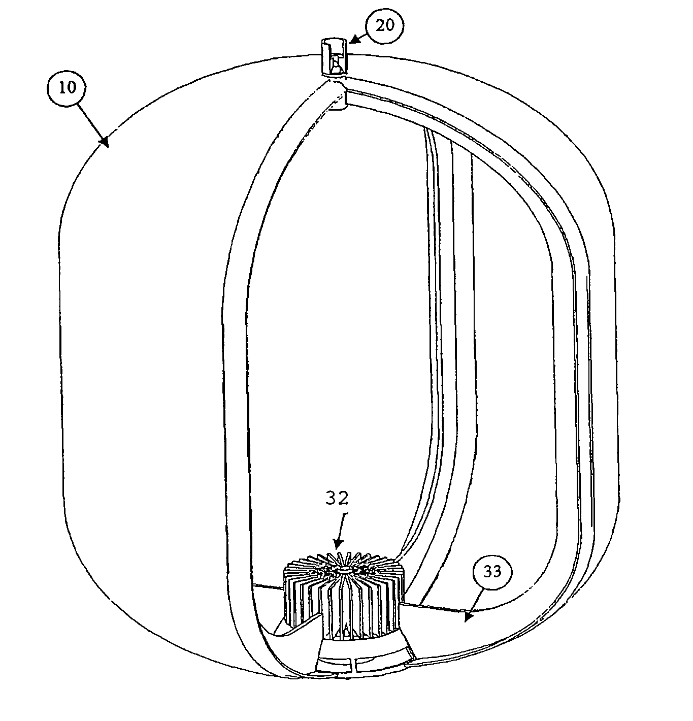
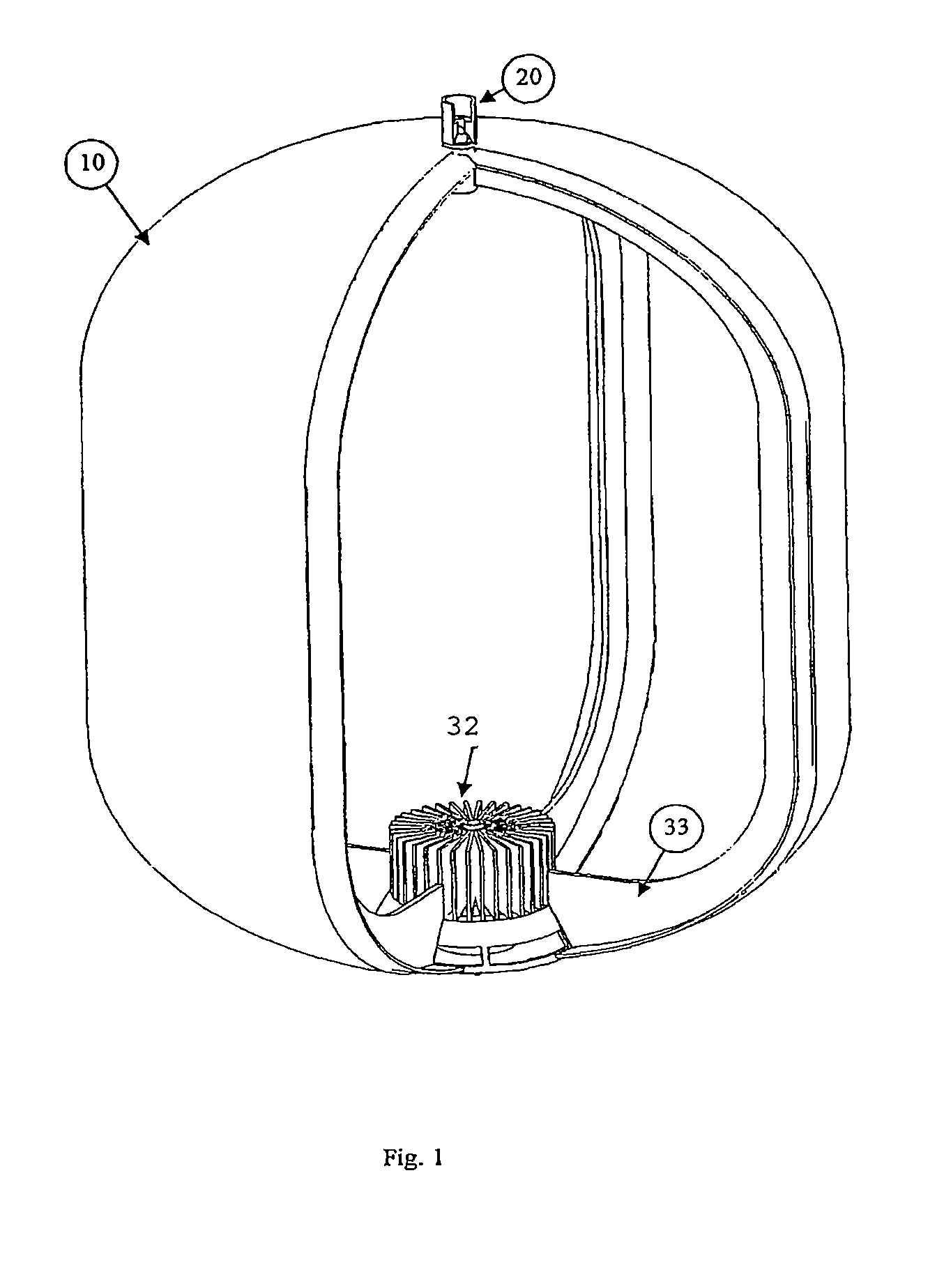
[0025]The liner typically has cylindrical or spherical shape and it is moulded in two parts: the lower dome and the upper dome.

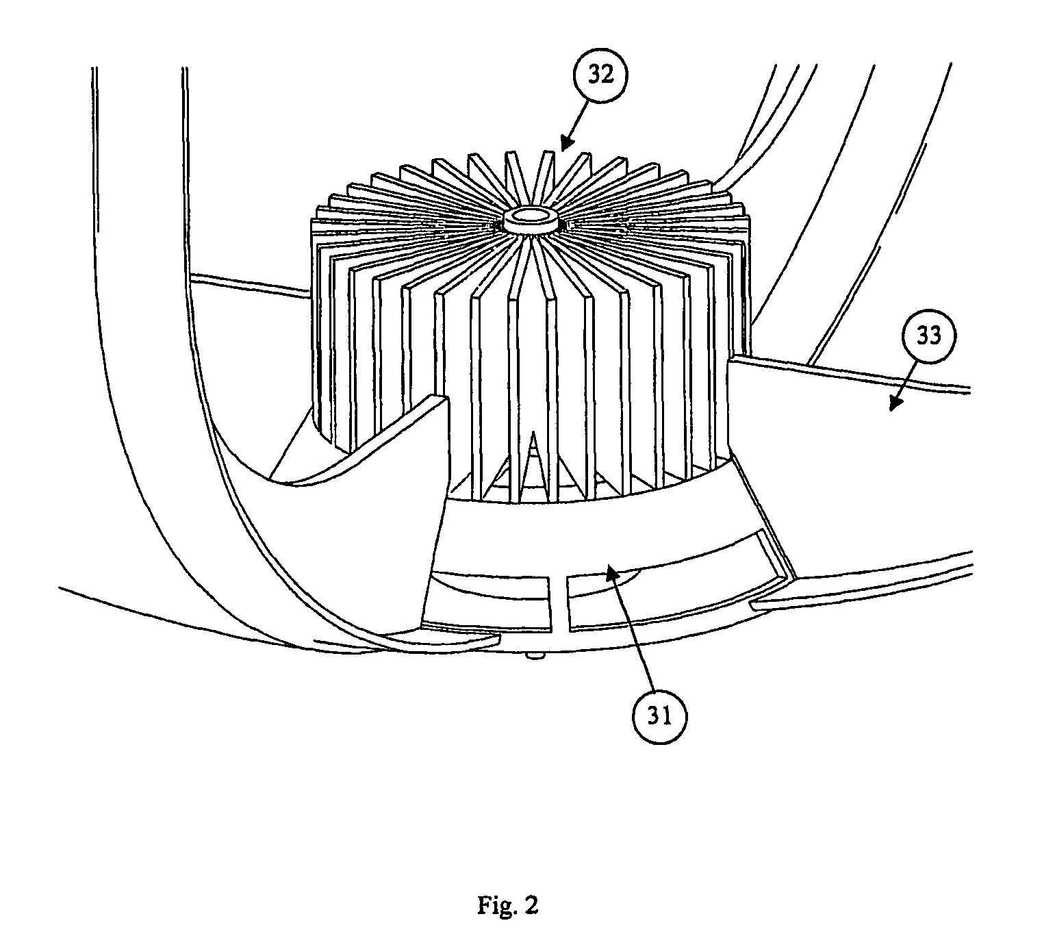
[0026]The lower dome incorporates the components of the propellant distribution device: sump, liquid trap and bulkheads.

[0027]Being integrated with the dome, these components are integral parts thereof and manufactured by means of the sam...


PUM

PropertyMeasurementUnit
compatibilityaaaaaaaaaa
weightaaaaaaaaaa
pressureaaaaaaaaaa

Abstract

The present invention relates to propellant tanks for space platforms, launchers and every sort of space transport craft.

Description

[0001]The present invention relates to propellant tanks for space platforms, launchers and every sort of space transport craft.[0002]More specifically, the present invention relates to the need to decrease the launch mass of the space vehicle, to reduce production and development costs and, simultaneously, to reduce the time required for commissioning a tank.ASSOCIATED TECHNOLOGY[0003]Tanks for transporting propellant are used to store the two components of the hypergolic mixture (fuel and oxidiser), aboard the space vehicle, throughout its operating life.[0004]The constituents of the hypergolic mixture must be fed to the engines at a well defined supply pressure.[0005]This specific function is carried out using pressurising gases, normally inert gases, which thus assure compatibility with the propellant.[0006]To avoid the ingestion of gas bubbles into the engines, which can generate their malfunction, it is necessary to separate the liquid phase of the propellant from the gaseous p...

Claims


Application Information

Patent Timeline
Patent Type & Authority Patents(United States)
IPC IPC(8): B01D47/00B67D7/72
CPCF17C13/088F17C2201/0104F17C2203/0604F17C2203/0658F17C2223/0153F17C2223/0161F17C2270/0194
Inventor PESSANA, MARIO
Owner LEONARDO
Why Eureka
Try Eureka