Method for surveillance of space/air space

a sensor system and air space technology, applied in the direction of reradiation, using reradiation, radio wave reradiation/reflection, etc., can solve the problems of insufficiently resolving the problem of only inadequately resolving the problem of measurement errors, difficult to associate targets that are flying physically closely together using known methods, and increasing the probability of incorrect association of measurement errors. , to achieve the effect of sufficient accurate association of targets and minimizing the time required

Inactive Publication Date: 2011-10-25
OERLIKON CONTRAVES BESCHRAENKTER HAFTUNG
View PDF19 Cites 1 Cited by
  • Summary
  • Abstract
  • Description
  • Claims
  • Application Information

AI Technical Summary

Benefits of technology

[0012]In this context, the object of the invention is to specify a method which all

Problems solved by technology

In particular, it is difficult to associate targets that are flying physically closely together using known methods.
Measurement errors relating to the position and velocity of a target are a major disturbance source for correct association.
Measurement errors increase the probability of incorrect associations.
The further aspect for errors occurs, as already mentioned, in the spatial resolution of the known 2D, 2.5D sensors which cannot resolve one of the three spatial dimensions at all, or can resolve it only inadequately.
In contrast, passive electro-optic

Method used


Image

  • Method for surveillance of space/air space
  • Method for surveillance of space/air space
  • Method for surveillance of space/air space

Examples


Embodiment Construction

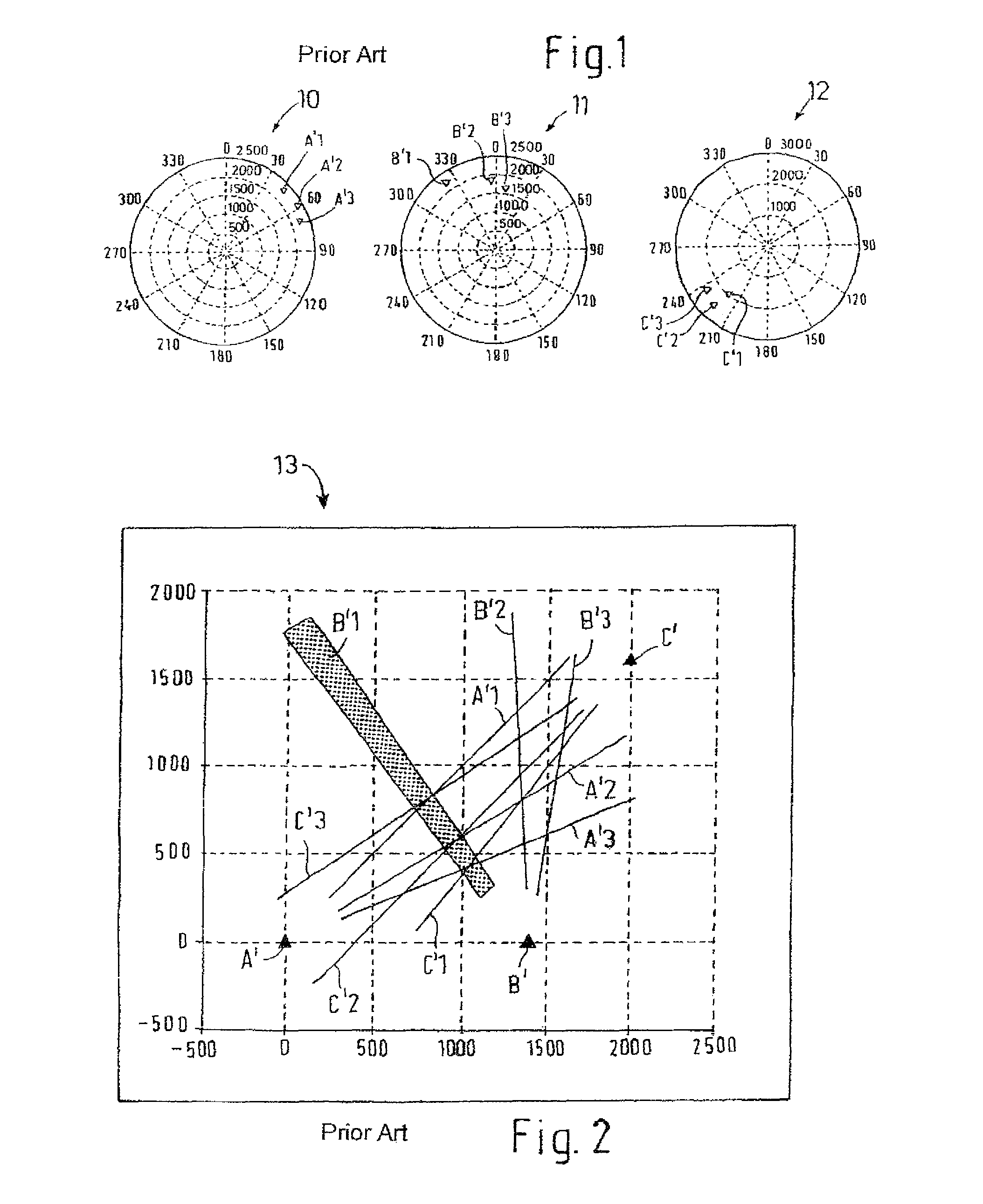
[0027]FIG. 1 shows a display 10 of a first search radar sensor A and a further display 11 of a second search radar sensor B, as well as a third display 12 of a third search radar sensor C according to the prior art. The range (in meters) and direction (in degrees) are shown on the display 10. Three targets are indicated, as A1-A3. Three targets are indicated as B1-B3 on the display 11 of the second search radar sensor B, and three targets are indicated as C1-C3 on the display 12 of the third search radar sensor C.

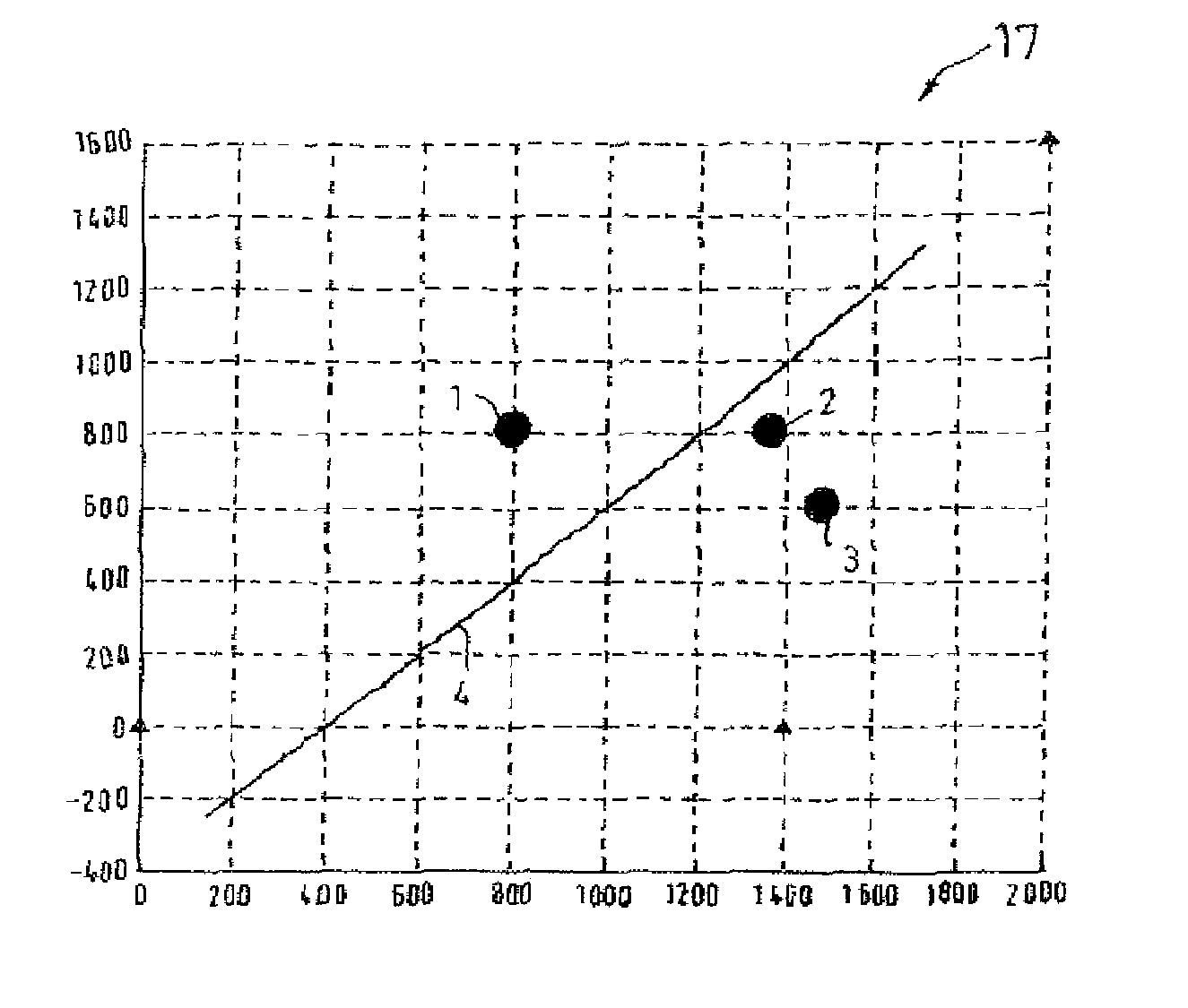
[0028]For correlation purposes, the measurements are converted to the geometry 13 of the higher-level Cartesian coordinate system. The position of each of the sensors A, B, C is required for this purpose.

[0029]FIG. 2 shows the illustration, as known from the prior art, of the measurement from FIG. 1 in the higher-level system. The radar positions which result in the display / geometries of the displays 10 to 12 are identified by A, B, C. In this case, the measurements are map...


PUM


Abstract

The invention proposes utilizing the known geometry of the measurements in order to assign them to one another and to resolve ambiguities, wherein the 3D position of an object (3) in space is determined by a spatial section at the same time. This is done using a plurality (N) of sensors (A, B, C) and their geometries (10, 11, 12), wherein a first sensor (A) is part of the master sensor and a space curve (A1) is calculated and then transmitted to the geometry (11) of a sensor (B) which is defined as a slave sensor and whose local geometry (11) is taken into account, a further sensor (C) is then defined as a slave in which the space curves (B1-B3) of the correspondence obtained in the preceding step are calculated and transmitted to the geometry (12) of the new slave sensor (C) together with the master curve (A1), wherein the steps are repeated at least until the last (N) remaining sensor is defined as a slave in a last step (N−1) and the master (A1) and all of its associated measurements of the previous slave sensors (B, C) are transmitted to the local geometry of the last (N) slave sensor and compared with the measurements.

Description

[0001]This is a U.S. National Stage of application No. PCT / EP2006 / 007127, filed on Jul. 20, 2006. Priority is claimed on that application and on the following application:[0002]Country: Germany, Application No.: 10 2005 041 705.1 Filed: Sept. 2, 2005.BACKGROUND OF THE INVENTION[0003]The invention relates to a method for association of 2D measurements from a sensor system, in particular for air defense.[0004]EP 0 205 794 A1 discloses a surveillance system such as this for space / airspace surveillance. The real targets which are produced as video signals by an IR position-finding appliance during each search cycle are preprocessed in a data preprocessing device, and are discriminated and stored in an IR signal processor on the basis of their elevation values and azimuth values. The real-target coordinates in elevation, azimuth and distance, as determined by the appliances, are supplied to a higher-level fire control facility.[0005]A radar measurement device for airspace monitoring is d...

Claims


Application Information

Patent Timeline
IPC IPC(8): G01S13/87
CPCG01S7/2955G01S13/87
Inventor HONIKEL, MARCBERGER, HANSPETER
Owner OERLIKON CONTRAVES BESCHRAENKTER HAFTUNG
Why Eureka
Try Eureka