System and method for correcting global navigation satellite system pseudorange measurements in receivers having controlled reception pattern antennas

a global navigation satellite and pseudo-range technology, applied in the field of global navigation satellite systems, can solve problems such as common range error, range error, and other effects that contribute to range measurement error still remain

Active Publication Date: 2011-10-25
RAYTHEON CO
View PDF30 Cites 25 Cited by
  • Summary
  • Abstract
  • Description
  • Claims
  • Application Information

AI Technical Summary

Problems solved by technology

This clock error is common to all measurements since the atomic satellite clocks are all synchronized, and results in a common range error.
Other effects that give rise to range errors include atmospheric, multipath, and receiver and antenna hardware.
Nonetheless, other effects that contribute to range measurement errors still remain.
Atmospheric (i.e., tropospheric and ionospheric) delays are usually the next most significant source of error.
There are still other effects, most notably receiver antenna hardware, which cannot be compensated through any of the above techniques.
To the extent that such effects, such as directionally dependent group delay errors, are not common between different satellites (common errors disappear as part of the clock bias correction calculated when determining location), they can affect the accuracy of the resulting positional calculation.
Multiple element receiver antennas add complexity to the mitigation of these non-common errors, because the directionally dependent group delay errors may differ between antenna elements.
Each hardware path contributes a different delay to the overall measured time of reception.
Because the satellite signals are relatively weak, it is fairly straightforward to intentionally jam such signals, either by increasing the noise floor by transmitting broadband noise or by attempting to exceed the dynamic range of the receiver hardware with powerful narrowband signals.
This is unacceptable for military applications, so they rely on encrypted signals to thwart any spoofed transmissions, but are still susceptible to intentional interference on the same frequencies.
Intentional interference is usually significantly stronger than actual satellite transmissions.
However, for the complex case of a GNSS receiver employing a CRPA and dynamic beam steering, the multiplicity of combinations of antenna element outputs makes compensation of directionally dependent antenna induced errors more difficult, as the simple subtraction that might be used for FRPA compensation does not work with a CRPA.
Compensation of pseudorange measurements for such errors is a problem not addressed in previous GNSS CRPA beam steering sensors.

Method used


Image

  • System and method for correcting global navigation satellite system pseudorange measurements in receivers having controlled reception pattern antennas
  • System and method for correcting global navigation satellite system pseudorange measurements in receivers having controlled reception pattern antennas
  • System and method for correcting global navigation satellite system pseudorange measurements in receivers having controlled reception pattern antennas

Examples


embodiment

Frequency-Independent Embodiment

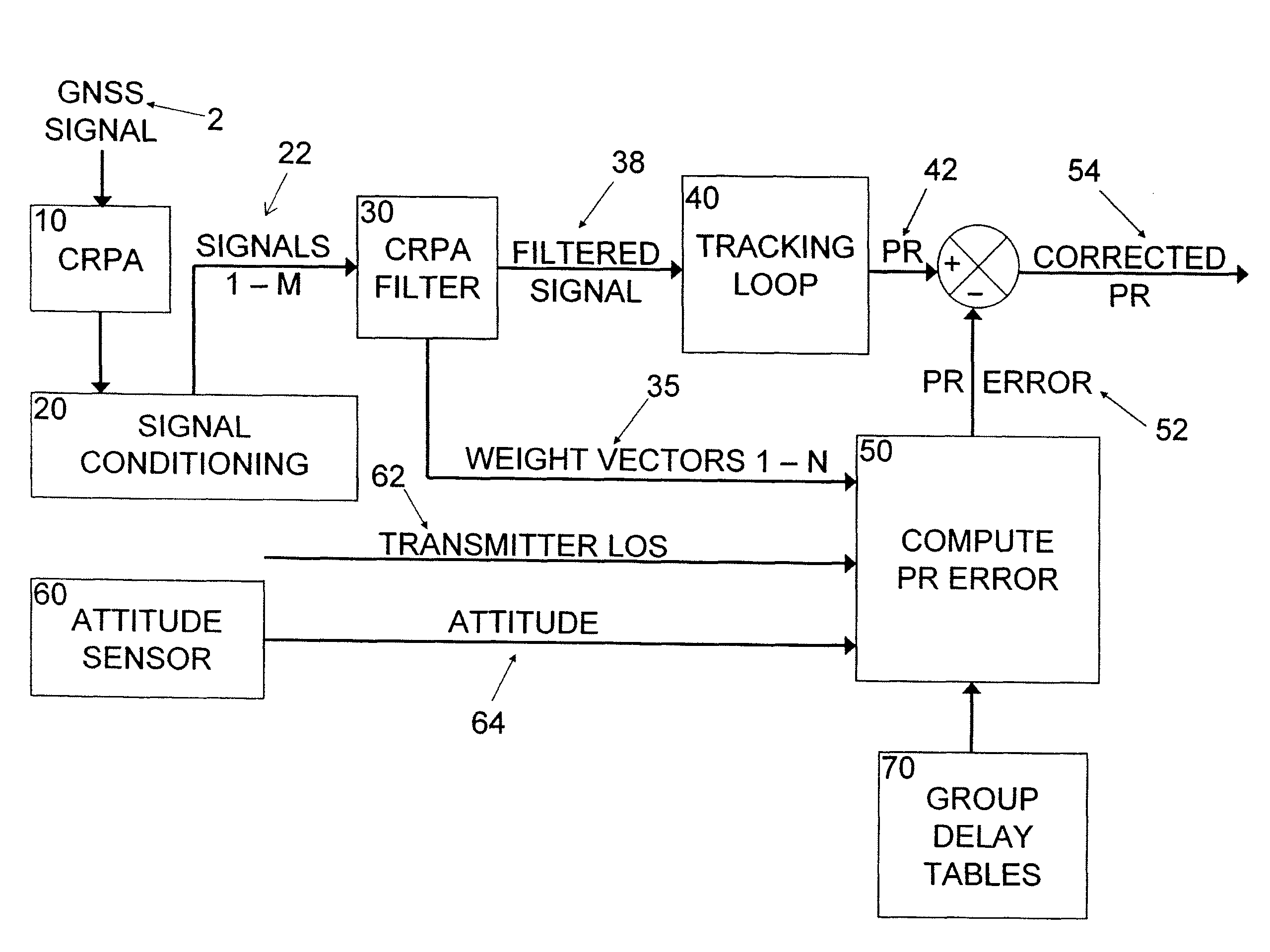
[0060]As a first approximation, assume there is no jamming or the jamming is broadband noise that has a constant power spectral density in the GNSS band. In either case, ABF will compute the same weight vector in every frequency bin if the receiver's thermal noise is white. If the weight vector is independent of frequency, ABF and CBF may be modeled in the time domain and their DFT 32 and inverse DFT 36 operations may be ignored.

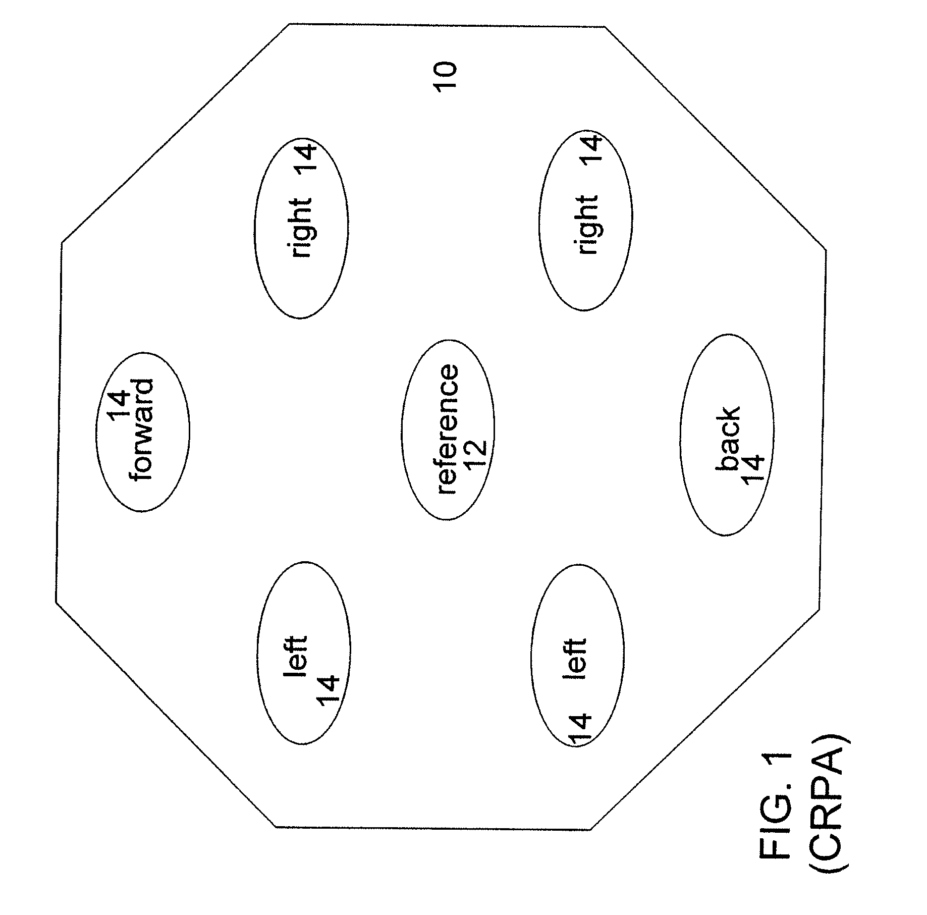
[0061]The complex signal received by the CRPA reference element 12 is u(t)=P(t)ei(ωt+φ), where P is the message code (±1), ω is the carrier frequency, and φ is the carrier phase. The signal received by the mth antenna element is time-shifted by Δtm relative to the reference element (|Δtm|m and shift its phase by θm:

u(t+Δtm−τm)=P(t+Δtm−τm)ei(ωt+ωΔtm−ωτm+φ+θm)

[0062]The antenna's contribution to θm is sensitive enough to the signal direction that a “sky map” (a table of phase versus azimuth and elevation) is needed to compute it....


PUM


Abstract

Global Navigation Satellite System (GNSS) pseudorange measurements are compensated for receiver hardware and directionally dependent antenna errors to obtain desired accuracies for high precision GNSS positioning applications using a multiple element controlled reception pattern antenna (CRPA). Pseudorange errors are calibrated and stored in a sky map by azimuth, elevation, radio frequency (RF) channel, and frequency. Corrections are applied in real time to each pseudorange measurement by applying a combination of the stored errors. The coefficients of the errors in the combination are computed as a function of steering vectors and CRPA filter weights. This implements a generalized pseudorange correction able to compensate a GNSS CRPA sensor for channel dependent errors such as group delay for both the case of uniform weights for all frequencies and the more complex case of frequency-dependent weights.

Description

STATEMENT REGARDING FEDERALLY SPONSORED RESEARCH OR DEVELOPMENT[0001]This invention was made with government support under Contract No. N00019-02-C-3002 awarded by the Department of the Navy. The government has certain rights to this invention.CROSS-REFERENCE TO RELATED APPLICATION(S)[0002]This application is related to U.S. patent application entitled “SYSTEM AND METHOD FOR CORRECTING GLOBAL NAVIGATION SATELLITE SYSTEM CARRIER PHASE MEASUREMENTS IN RECEIVERS HAVING CONTROLLED RECEPTION PATTERN ANTENNAS,” filed <concurrently herewith>, the entire content of which is incorporated herein by reference.BACKGROUND OF THE INVENTION[0003]1. Field of the Invention[0004]The present invention relates to the field of Global Navigation Satellite Systems (GNSS), such as the Global Positioning System (GPS), and, more particularly, to range measurement corrections in such systems.[0005]2. Description of the Related Art[0006]Global Navigation Satellite Systems (GNSS) use a constellation of di...

Claims


Application Information

Patent Timeline
Patent Type & Authority Patents(United States)
IPC IPC(8): H01Q3/26G01S19/23G01S19/37
CPCG01S19/23
Inventor MAENPA, JON E.HAUTZIK, ANDREW M.SAIN, PATRICK M.
Owner RAYTHEON CO
Why Eureka
Try Eureka