
Operating device, image display system, map display controller and program for map display controller

a technology of image display system and map display controller, which is applied in the direction of mechanical control devices, instruments, manual control with single controlling member, etc., can solve the problems of difficult to make the grip thinner, the map display device requires complicated operation to set, and the operation of the operating device can only perform one kind of input, so as to reduce the size of the operating device below the end of the grip, reduce the sensitivity, and reduce the inclination of the grip

Active Publication Date: 2011-10-25
DENSO CORP
View PDF18 Cites 9 Cited by
  • Summary
  • Abstract
  • Description
  • Claims
  • Application Information

AI Technical Summary

Benefits of technology

The present invention provides a technology that allows multiple inputs through a single operation performed with a hand gripping an operating device. The device can sense the inclination of the grip at a point remote from the supporting points and adjust the center of inclination to the grip. The device can also display an image of a map or map display in a way that allows the user to look down the map from a different viewpoint. This improves the visibility of the map and enhances the user's experience.

Problems solved by technology

However, this operating device can perform only a single kind of input through the single operation performed by the user with the hand gripping the grip of the operating device.
Accordingly, it has been difficult to make the grip thinner.
However, the map display device requires complicated operations to set the height of the viewpoint, the looking-down angle and the like.

Method used


Image

  • Operating device, image display system, map display controller and program for map display controller
  • Operating device, image display system, map display controller and program for map display controller
  • Operating device, image display system, map display controller and program for map display controller

Examples


Embodiment Construction

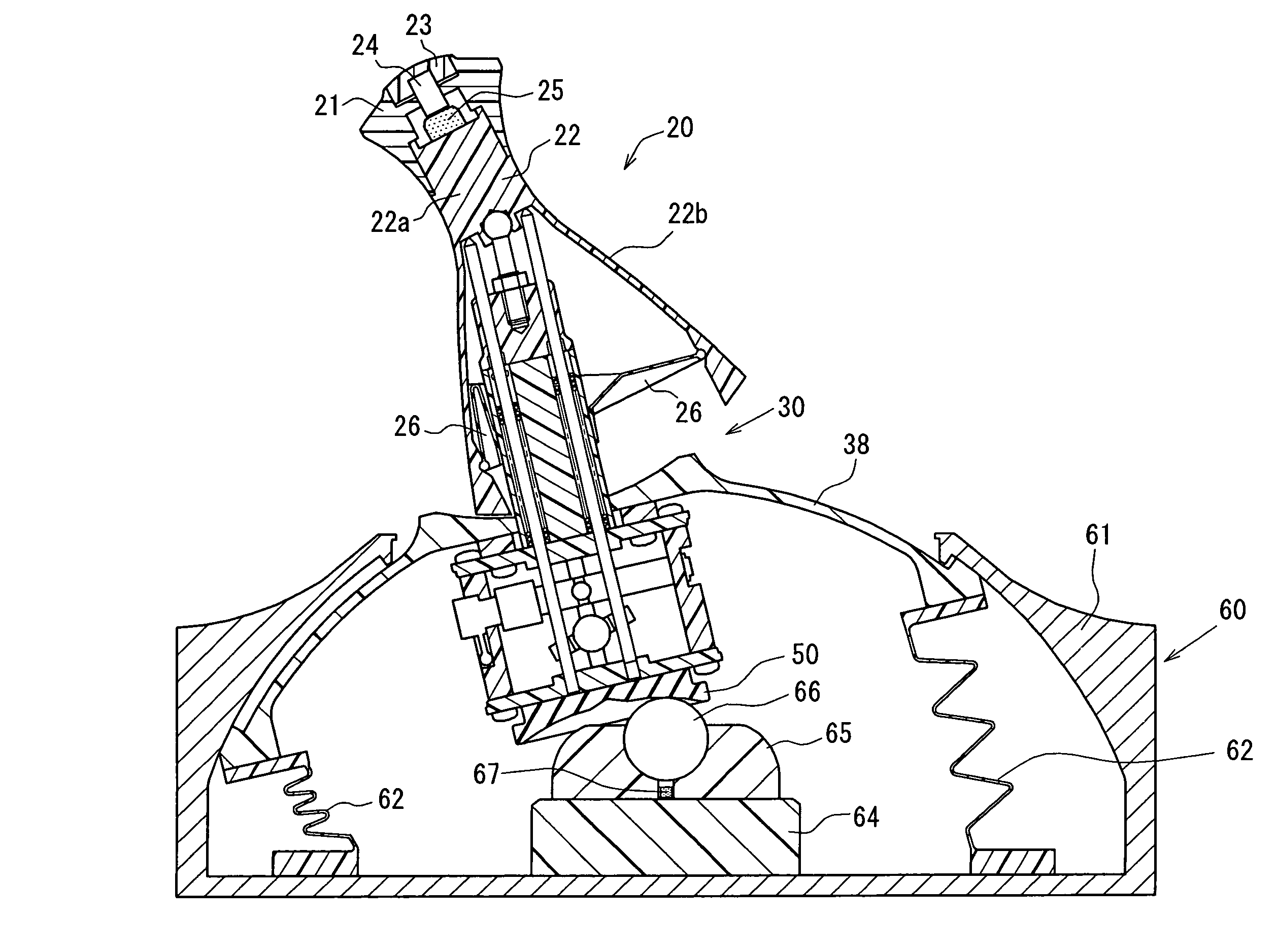
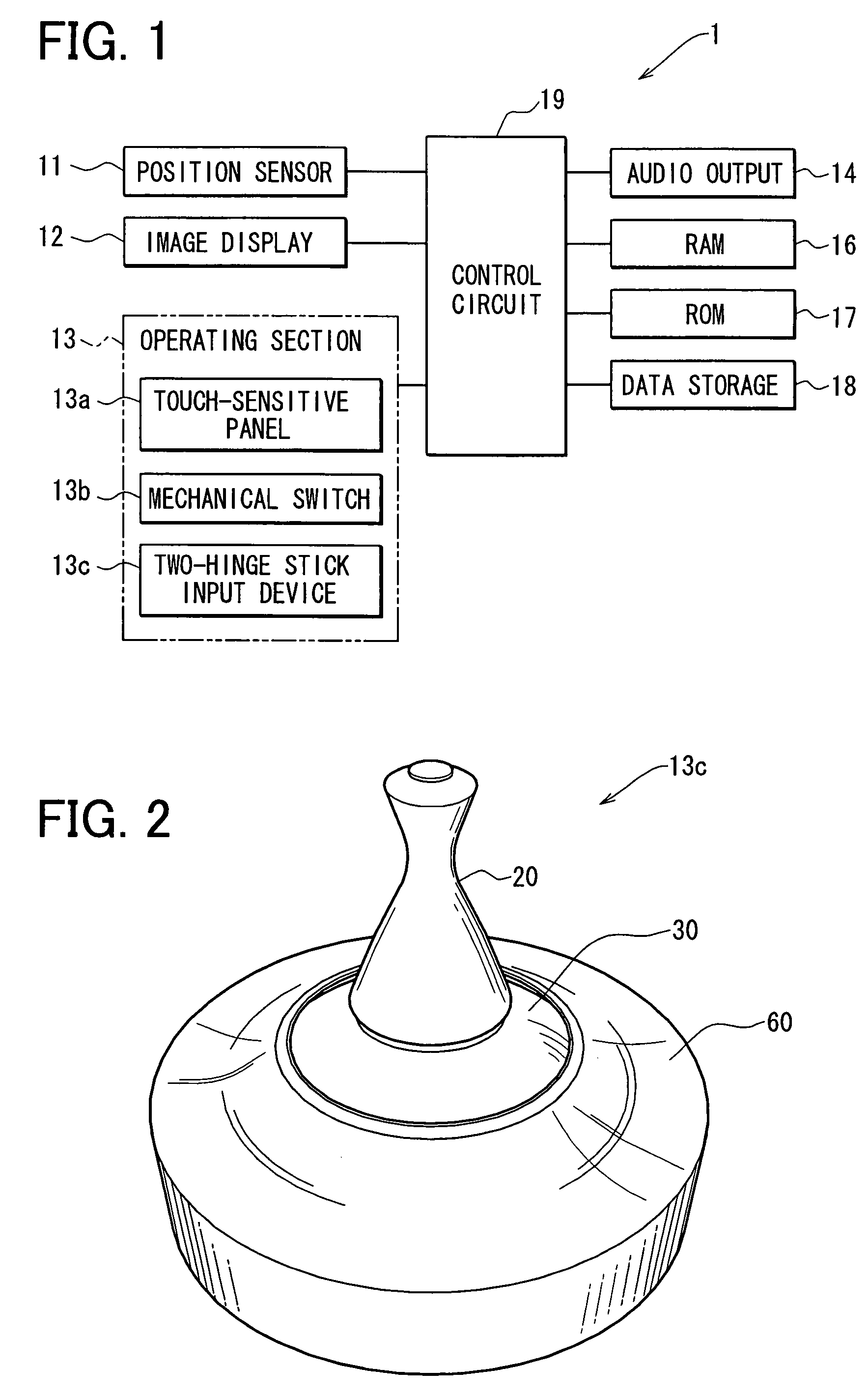
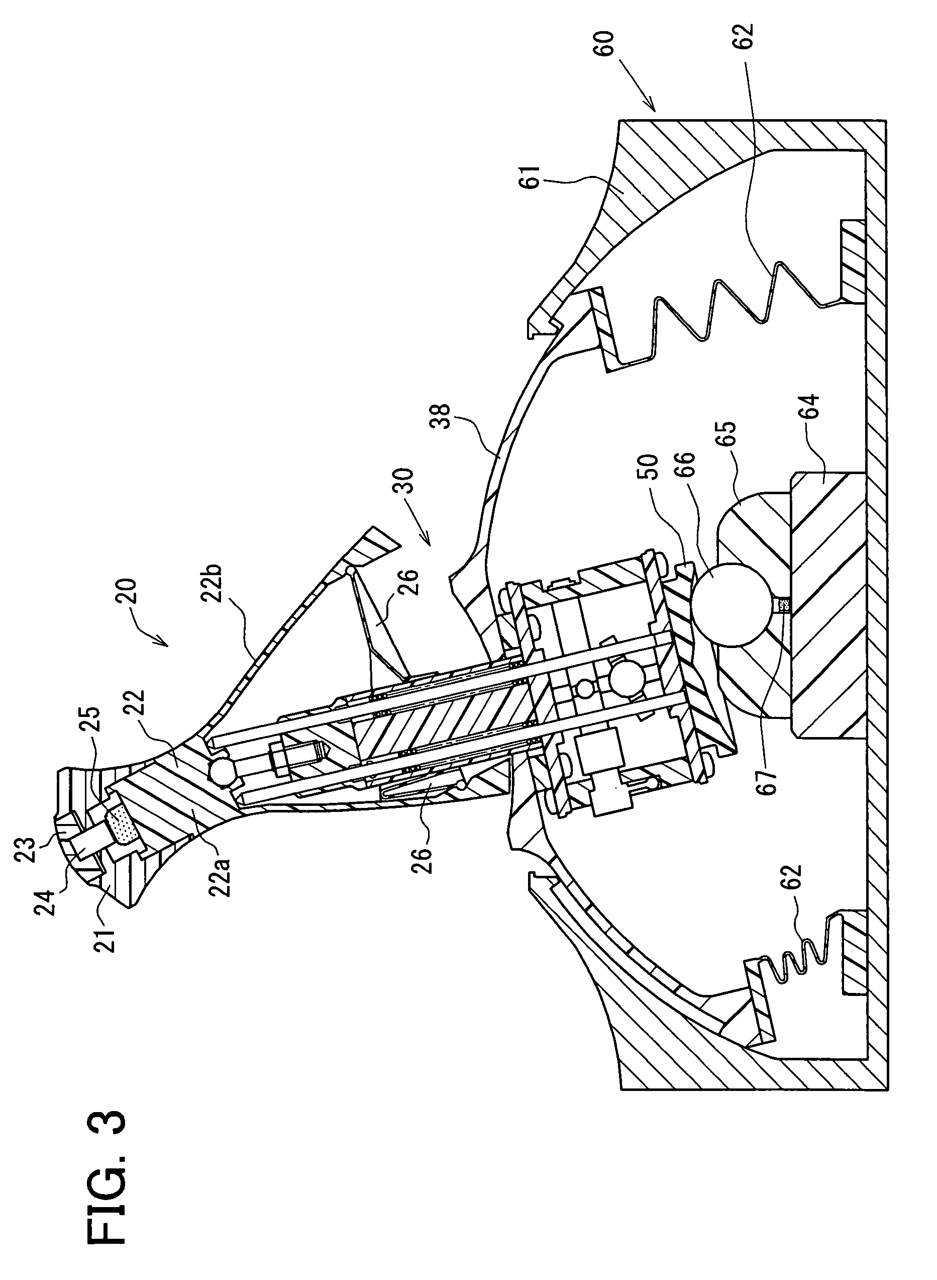
[0049]Referring to FIG. 1, a hardware structure of a vehicle navigation system 1 according to a first example embodiment of the present invention is illustrated. The vehicle navigation system 1 has a position sensor 11, an image display device 12, an operating section 13, an audio output device 14, a RAM 16, a ROM 17, a data storage section 18 and a control circuit 19. The position sensor 11 has sensors (not shown) such as an earth magnetism sensor, a gyroscope, a vehicle speed sensor and a GPS signal receiver. The position sensor 11 outputs information for specifying a present position and a bearing of the vehicle based on various properties of the sensors to the control circuit 19. The image display device 12 displays an image to a user based on an image signal outputted from the control circuit 19. For example, the displayed image is a map centering on the present position. The audio output device 14 outputs an audio signal as a sound based on audio data transmitted from the cont...


PUM


Abstract

An image display system has an operating device, a specifying device and an image display device. If the operating device receives a single operation from an exterior (i.e., from user), the operating device outputs first and second signals based on the single operation. The specifying device specifies a viewpoint and a sight line direction to look down a picture based on the first and second signals outputted by the operating device. The image display device displays an image of the picture in such a manner that the picture is looked down from the viewpoint in the sight line direction specified by the specifying device. As a result, the operation for adjusting the viewpoint and the sight line direction is facilitated.

Description

CROSS REFERENCE TO RELATED APPLICATION[0001]This application is based on and incorporates herein by reference Japanese Patent Application No. 2006-92366 filed on Mar. 29, 2006.BACKGROUND OF THE INVENTION[0002]1. Field of the Invention[0003]The present invention relates to an operating device, an image display system, a map display controller, and a program for the map display controller.[0004]2. Description of Related Art[0005]A user of an operating device described in JP-A-2003-99139 can perform two or more inputs with the single operating device by gripping and tilting a grip main body and by tilting a small lever provided on an upper portion of the grip main body with the thumb. However, this operating device can perform only a single kind of input through the single operation performed by the user with the hand gripping the grip of the operating device. The second kind of input is realized by additional motion of the thumb.[0006]Conventionally, a device for sensing an inclinatio...

Claims


Application Information

Patent Timeline
Patent Type & Authority Patents(United States)
IPC IPC(8): G09G5/08G06F3/0338
CPCG05G25/04Y10T74/20201G05G2009/04774
Inventor ARAI, RIEKOMORI, TOSHIFUMITAKEMORI, YOSHITERUYAMAGUCHI, TERUAKIHARADA, TAKUJIICHIKAWA, YOSHIKATSUSUGIURA, RYOUTAMURATA, RYOSUKE
Owner DENSO CORP
Learn More