
Method and apparatus for transmitting overhead information

a technology for overhead information and transmission methods, applied in electrical apparatus, time-division multiplexes, power management, etc., can solve problems such as system cost increase, error correction code efficiency, and coding gain reduction, and achieve the effect of reducing the requirement for receiving sensitivity and sensitivity of the receiver

Inactive Publication Date: 2011-10-25
HUAWEI TECH CO LTD
View PDF21 Cites 0 Cited by
  • Summary
  • Abstract
  • Description
  • Claims
  • Application Information

AI Technical Summary

Benefits of technology

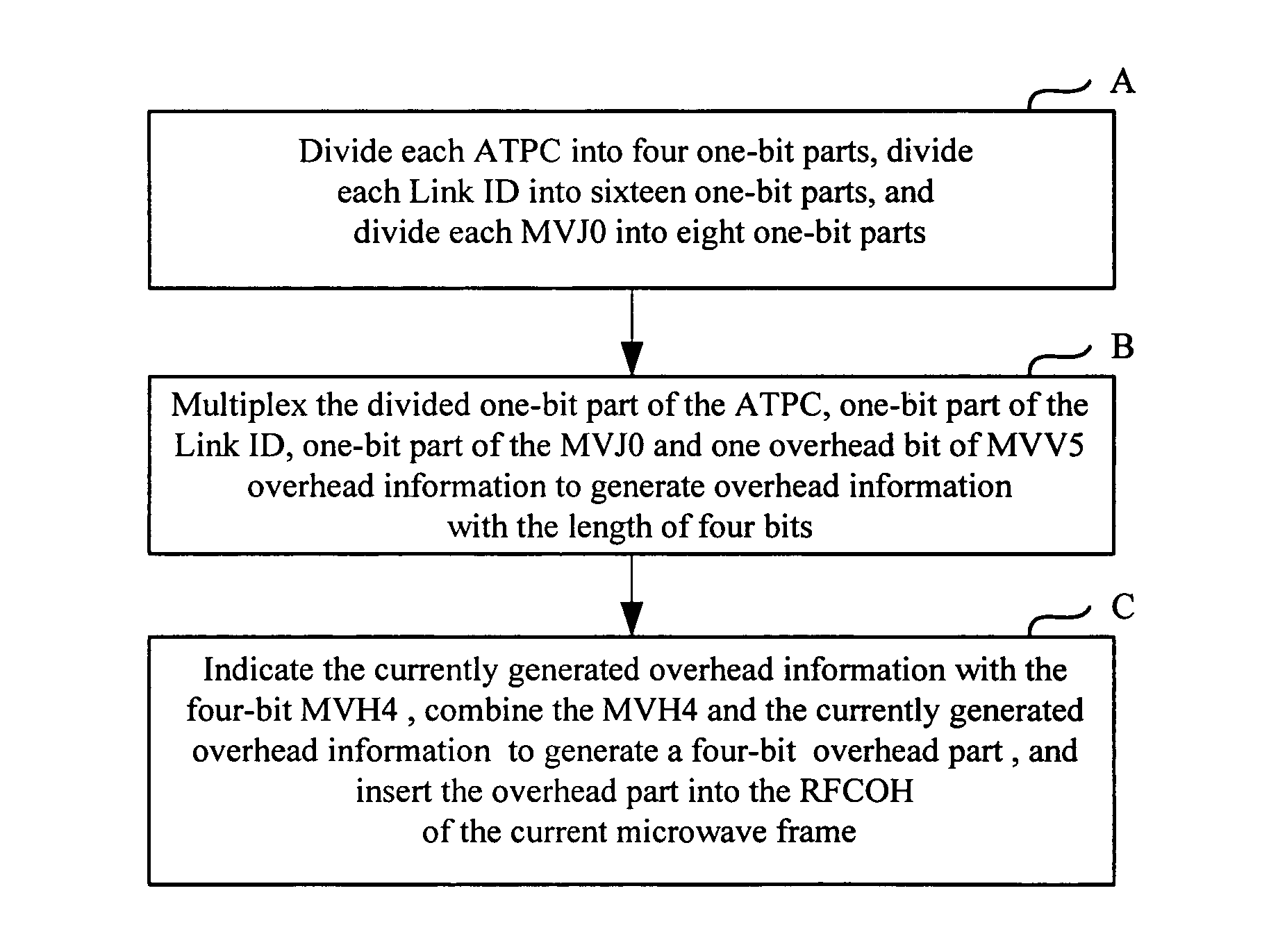
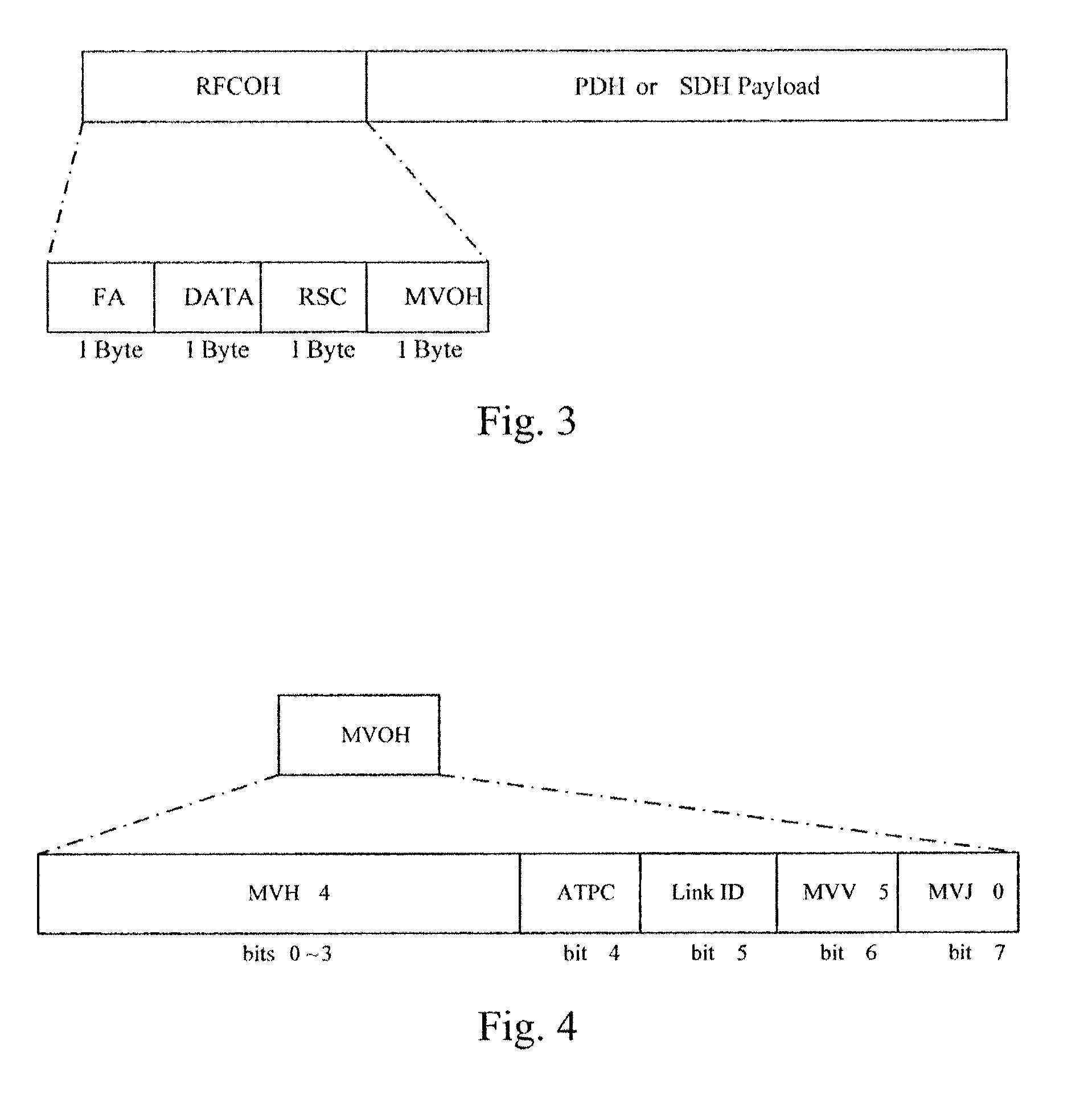
[0005]The embodiments of the present invention provide a method for transmitting overhead information, a method for receiving overhead information, an overhead information transmitting apparatus and an overhead information receiving apparatus. With the methods and the apparatus, plenty of overhead bytes can be transmitted in an available transmission bandwidth and the requirement on the receiving sensitivity of a receiver can also be reduced. Therefore, the contradiction among the transmission bandwidth, the transmission of an overhead byte and the receiving sensitivity of the receiver is solved.
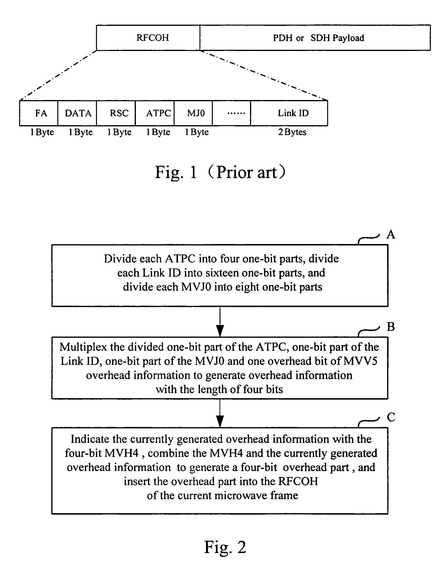
[0018]As can be seen, if the existing overhead information transmission method is used, transmission of each microwave frame overhead occupies a relatively large transmission bandwidth, for example, for four paths of E1 services modulated by the QPSK mode, the overhead of the Link ID occupies 1.5% of the channel bandwidth. In this way, on the premise of meeting the requirement of channel bandwidth in the recommendation and regulation formulated by the ETSI, because the overhead byte of the microwave frame occupies relatively large channel bandwidth, an error correction byte in the Payload of each microwave frame for correcting the transmitted information is reduced. The reduction of the error correction code efficiency leads to the reduction of the coding gain, which puts forward a relatively high requirement for the receiving sensitivity of a receiver and leads to the increase of system cost. By using the feature that some overhead bytes of the microwave frame overhead do not need to be transmitted in a high speed adequately, embodiments of the present invention divide the overhead bytes into several parts, and transmit the divided overhead bytes in multiple microwave frames so as to greatly reduce the channel bandwidth occupied by the overhead bytes of each microwave frame. With the method provided by embodiments of the present invention, the saved channel bandwidth may be used for performing the error correction code on the transmitted information, so as to improve the coding gain, reduce the requirement for the receiving sensitivity of the receiver, and reduce the cost of the microwave transmission system eventually.

Problems solved by technology

The reduction of the error correction code efficiency leads to the reduction of the coding gain, which puts forward a relatively high requirement for the receiving sensitivity of a receiver and leads to the increase of system cost.

Method used


Image

  • Method and apparatus for transmitting overhead information
  • Method and apparatus for transmitting overhead information
  • Method and apparatus for transmitting overhead information

Examples


Embodiment Construction

[0025]The present invention is further described as follows in detail with reference to the accompanying drawings as well as embodiments so as to make the technical solution and merits of the present invention more apparent.

[0026]In a microwave frame overhead byte, a Link ID is mainly used for indicating a microwave transmission link during microwave transmission; the Link ID is an identity number of a microwave link which connects a receiver and a transmitter. At present, the Link ID that should be transmitted or received by a microwave link may be set via software. If a practically received Link ID is different from a Link ID that should be received by a microwave link, a Link ID mismatch alarm is generated for indicating that there is a code error in the Link ID of the microwave link or a microwave signal of an illegal microwave link in reception. Taking the complex condition of a whole network into consideration, Link IDs of 4094 microwave links from 1 to 4094 are defined, and s...


PUM


Abstract

A method provided by the present invention for transmitting overhead information, includes dividing and reforming overhead information into at least two overhead parts, inserting the at least two overhead parts into overhead bytes of at least two corresponding data frames, and transmitting the at least two overhead parts via the at least two data frames which are microwave frames. Overhead information transmitting apparatus and overhead information receiving apparatus are also provided by the present invention. With the method and apparatus of the present invention, the channel bandwidth resources occupied by the overhead bytes or each microwave frame are greatly reduced. If the saved channel bandwidth is used for performing the error correction code on the transmitted information, the code gain is improved and the sensitivity requirement on the receiver is reduced so that the cost of a microwave transmitting system is reduced eventually.

Description

CROSS-REFERENCE TO RELATED APPLICATIONS[0001]This is a continuation of International Application No. PCT / CN2006 / 003330, filed Dec. 7, 2006, which claims the priority benefit of Chinese Patent Application No. 200610057918.5, filed Feb. 27, 2006, the entire respective disclosures of which are incorporated herein by reference.FIELD OF THE INVENTION[0002]The present invention relates to microwave transmission technologies, and particularly, to a method for transmitting overhead information, a method for receiving overhead information, overhead information transmitting apparatus and overhead information receiving apparatus.BACKGROUND OF THE INVENTION[0003]In the field of microwave transmission technologies, strict requirements have been put forward on channel bandwidth occupied by transmitting services with different rates. For example, if four paths of E1 services at a central frequency of 13 GHz are transmitted in Quaternary Phase Shift Keying (QPSK) mode, the European Telecommunicatio...

Claims


Application Information

Patent Timeline
Patent Type & Authority Patents(United States)
IPC IPC(8): H04J3/24
CPCH04J3/1611H04W52/58H04J2203/0035
Inventor HUANG, JIANBINWANG, TIANXIANGQIU, ZHIYONGZHAO, GUIXUEZHANG, FENGFENG, JUNLI, DEJUNTU, YONGJUNSONG, XIAOBIN
Owner HUAWEI TECH CO LTD
Learn More