
Headset power management

a headband switch and power management technology, applied in the field of headband power management, can solve the problems of long-term reliability problems, large volume of mechanical headband switch, and inability to transfer mechanical headband switch approaches to non-headband based headsets such as single-ear devices, and achieve the effect of reducing power consumption

Active Publication Date: 2011-10-25
ATMEL CORP
View PDF37 Cites 30 Cited by
  • Summary
  • Abstract
  • Description
  • Claims
  • Application Information

AI Technical Summary

Benefits of technology

The capacitive sensing system provides a reliable, cost-effective, and adaptable solution for reducing power consumption in headsets by accurately detecting user presence, enhancing battery life and usability across various environmental conditions.

Problems solved by technology

This has increased pressure on engineers to consider how most efficiently to use the electrical power available, particularly for cordless battery-operated headsets where battery life and available power are limited.
While these known power-saving headsets fulfil the desired function, they are not without various drawbacks.
For example, mechanical switches are relatively bulky and expensive, and they can also suffer from long-term reliability problems.
Moreover, the mechanical headband switch approach is not transferable to non-headband based headsets such as single-ear devices, for example ones that operate wirelessly by Bluetooth™ or otherwise.
Sensing user presence based upon detecting inductive noise is also less than ideal, particularly given the random nature of such noise and its amplitude variability according to differing physical conditions, such as the degree of electrode contact with the user (e.g. if a user is jogging), prevailing environmental conditions (e.g. if a user is sweating or is exposed to rain), etc.

Method used


Image

  • Headset power management
  • Headset power management
  • Headset power management

Examples


Embodiment Construction

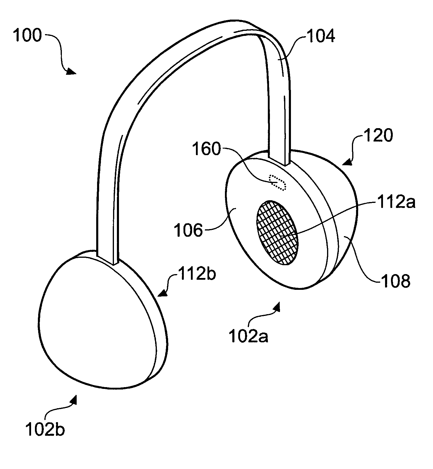
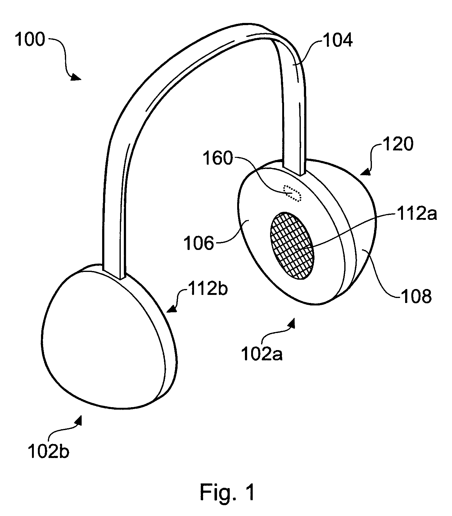
[0047]FIG. 1 shows a schematic diagram of an energy saving headset 100. The headset 100 comprises first and second casings 102a and 102b housing respective loudspeakers 112a and 112b for reproducing stereo sound. The casings 102a and 102b are physically connected together by a headband 104 that comprises a recess for housing electrical cabling (not shown) which connects the loudspeaker 112b in the second casing 102b to headset electronics 120 housed in the first casing 102a.

[0048]The casings 102a and 102b are formed of an outer casing cover 108 and an inner cover 106 that contacts a user's ear when the headset 100 is being worn. The casing cover 108 may be used to mount various user operable controls (not shown), such as, for example, volume controls, channel controls etc. The cover 106 can be provided over padding for user comfort and be made from various materials, including, for example, a flexible water-resistant polymeric sheet material. An opening in the cover 106 exposes the...


PUM


Abstract

The invention relates to an energy saving headset 100. The headset 100 comprises a power management unit 150 that is operable to reduce the power consumption of the headset 100 when a user 110 is not present. The power management unit 150 uses capacitive sensing to detect the presence of the user 110. Capacitive sensing is advantageous since it provides a flexible and reliable sensor that can accurately detect the presence or absence of a user 110 either by detecting user proximity or user contact. Moreover, in various embodiments, the sensitivity of a capacitive sensor may be adjusted to account for user movement or changes in environmental conditions, such as, for example, the presence of water, or sweat, on the headset 100 to further improve sensing reliability. The invention further relates to headsets using user presence signals based on capacitive sensing to control other functions of the headset or to control external devices to which the headset is connected, either wirelessly or by wires.

Description

FIELD[0001]The invention relates to apparatus comprising headsets and more especially but not exclusively to power management and / or function control of such apparatus. In particular, the invention relates to power management in a headset that comprises one or more circuit elements that consume electrical power such as, for example, a Bluetooth™ or other wireless receiver.BACKGROUND[0002]Many different types of headsets have been designed by numerous manufacturers with various types of end user application in mind. For example, stereo headphones for listening to music have been around for many years, as have ear pieces for use with hearing aids, portable radios such as GB 1,483,829A, U.S. Pat. No. 5,678,202 and U.S. Pat. No. 6,356,644.[0003]Recently, many new types of headset that can be worn by a user have been developed with a view to using them with mobile cellular telephones or other portable electronic devices. Numerous headset designs have been created to enable a user to use ...

Claims


Application Information

Patent Timeline
Patent Type & Authority Patents(United States)
IPC IPC(8): H03B29/00H04R25/00
CPCH04R1/1041H04R1/10H04R5/033H04R2420/07H04R2430/01H04R2460/03H04R1/1008H03K17/955H04M1/73H04R3/00H04R5/04
Inventor PHILIPP, HARALD
Owner ATMEL CORP
Learn More