Load carriers for vehicles

a technology for loading carriers and vehicles, applied in the field of loading carriers, can solve the problems of complex construction of the load carrying arm, many storage problems still exist, and the load is large and therefore awkward to store or transpor

Active Publication Date: 2011-11-01
THULE SWEDEN AB
View PDF6 Cites 9 Cited by
  • Summary
  • Abstract
  • Description
  • Claims
  • Application Information

AI Technical Summary

Benefits of technology

[0010]In this manner, a collapsible arch is provided that comprises few components and that is easy to manufacture and easy for a user to assemble or disassemble.
[0011]When unlocked from said in-use position, said first and second arch parts may be substantially immediately pivotable by a single movement for each into their respective said storage positions. This saves time and keeps the operation easy for a user. The converse is also true for erection of the arch.
[0013]Said pivotal coupling may comprise a cam or groove and follower mechanism. Said pivotal coupling may comprise a shaft or tube portion that is rotatable in a sleeve portion, in which arrangement one of its parts defines a groove that interacts with a pin disposed in the other part and which groove has an inclination relative to the longitudinal axis of said pivotal coupling, with the effect that said parts of the shaft / tube and sleeve arrangement shift automatically relative to each other along the longitudinal axis of said pivotal coupling when the associated said arch part is pivoted.

Problems solved by technology

One problem with load carriers of the general type under consideration herein is that, when they are not in use, they are extremely bulky and therefore awkward to store or to transport.
However, the supporting arch is for the most part so high that, when folded down, it extends beyond the platform / loading frame, which means that many of the storage problems continue to exist.
Furthermore, construction of that arm is complicated and the technique used to connect the crossbar to the other support arm is basic and unsuited to the current market place for such products.
A further drawback with some previous load carriers is that arms used to connect the load carrier to the vehicle take up space when the load carrier is not in use.

Method used


Image

  • Load carriers for vehicles
  • Load carriers for vehicles
  • Load carriers for vehicles

Examples


Embodiment Construction

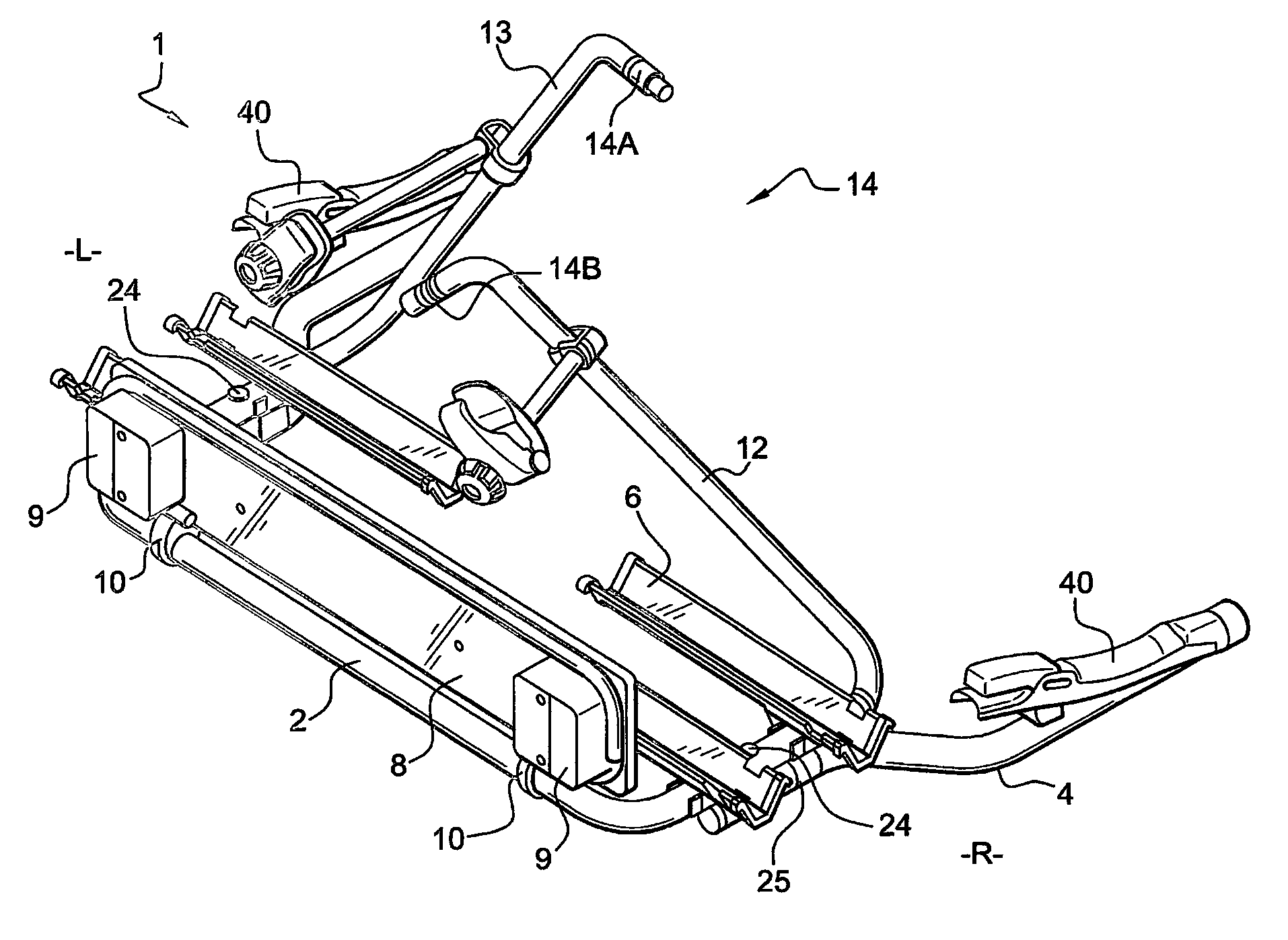
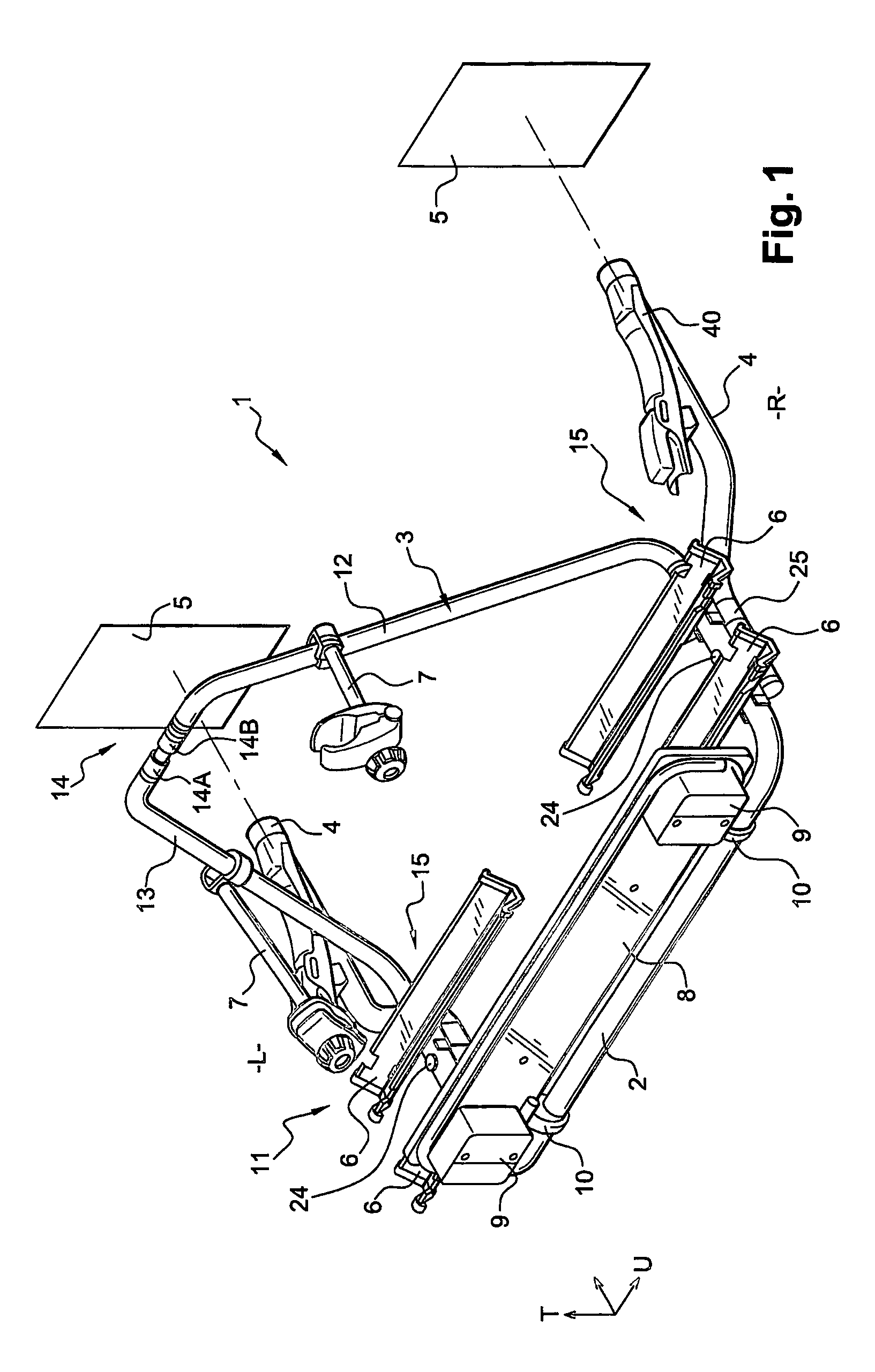
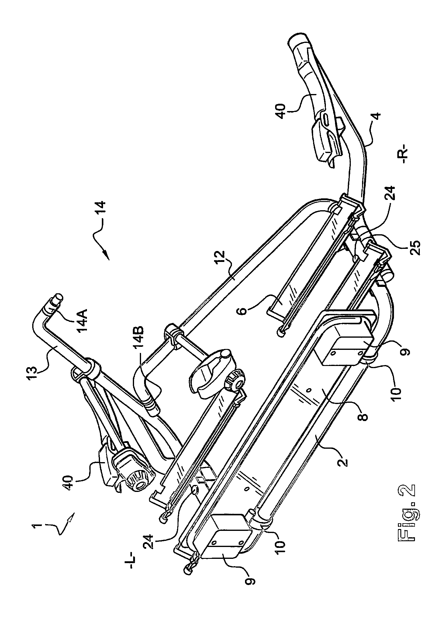
[0034]Referring to the figures, and in particular for the moment to FIGS. 1 and 4, a load carrier 1 according to an exemplary and non-limiting embodiment of the present invention is illustrated in a fully assembled state. The load carrier 1 comprises a loading frame 2, a supporting arch 3 and connecting members 4. Each of these parts 2, 3, 4 may be made from a round section material, for example from tubular metal. The load carrier 1 is intended to be connected by its connecting members 4 to a vehicle 5, preferably to its rear, which vehicle 5 is represented in the figure only by two rectangles 5. For connection to the vehicle, the connecting members 4 are provided at their vehicle-connection end with a manually operated coupling mechanism 40, each of which is configured to co-operate with an associated mounting point 5 of the vehicle.

[0035]Fitted to, or integrated with, the loading frame 2 are cargo members forming a cargo loading area 11. One example of the sort of cargo members e...


PUM


Abstract

A load carrier for coupling to a vehicle. The load carrier includes a loading frame and a supporting arch that extends substantially upwardly from and transversely to the loading frame. The supporting arch is divisible into first and second arch parts, each of which arch parts is pivotally coupled to the loading frame such that, when divided, each of the first and second arch parts is configured to be pivoted down to a storage position lying substantially level with the loading frame. The arch parts are configured to be interlocked to each other into an in-use position, in which the first and said second arch parts substantially alone form the supporting arch.

Description

BACKGROUND[0001]The present invention relates to a load carriers and in particular to a load carrier for coupling to a vehicle, such as might typically be coupled to the rear of a vehicle for the transport of bicycles or the like.[0002]It is known to provide a load carrier for a vehicle, and one known type of such a load carrier comprises a loading frame and a supporting arch extending upwardly from and substantially transversely to a loading area of the loading frame. This type of load carrier usually further comprises connecting members for coupling the load carrier to the rear of the vehicle.[0003]One particular prior art load carrier is disclosed in EP-1095820, which is adapted for connection to a tow hitch of the vehicle for carrying cargo such as bicycles. An inverted “U” shaped retaining bar rises from a platform of the load carrier and supports some bicycle holders.[0004]One problem with load carriers of the general type under consideration herein is that, when they are not ...

Claims


Application Information

Patent Timeline
Patent Type & Authority Patents(United States)
IPC IPC(8): B60P3/07B60R9/10B60R9/06
CPCB60R9/06B60R9/10Y10S224/924
Inventor PREMARTIN, ARNAUDVEUILLOT, OLIVIERODIN, HANSPERSSON, JOAKIM
Owner THULE SWEDEN AB
Why Eureka
Try Eureka