Continuously angle-adjustable multifunction tripod

a multi-functional, angle-adjustable technology, applied in the field of tripods, can solve the problems of failure to observe, inability to adapt to complex environments, and the existing tripods may not well meet the foregoing demands, so as to achieve convenient operation, convenient operation, and convenient use.

Inactive Publication Date: 2011-11-01
SUZHOU SYNTA OPTICAL TECH
View PDF8 Cites 43 Cited by
  • Summary
  • Abstract
  • Description
  • Claims
  • Application Information

AI Technical Summary

Benefits of technology

[0007]A primary object of the present invention is to provide a continuously angle-adjustable multifunction tripod with a simple and compact structure, convenient to operate, spans of the legs may be arbitrarily adjusted in a range from 0° to 180°, so that the tripod may be mounted quick and steadily in narrow space or an uneven terrain. The disadvantages of the prior art may be overcome.

Problems solved by technology

For example, for observation equipment, such as an astronomical telescope, during the observation, even the least dither or vibration may cause a failed observation.
Unfortunately, none of the existing tripods may well satisfy the foregoing demands.
Unfortunately, it is more difficult when using the tripod in an environment having more varied landforms and the tripod may need to be continuously fine tuned with respect to the spans of the legs.
Although the adjustment to the spans between the legs may be realized, the adjustment is also conducted by levels, and therefore the adjustment is very restricted and may not adapt to complex environments.
Further, the tripod employs many precise components, e.g., ratchets, for adjusting the opening angle of the legs, and thus the tripod is featured with a raised cost and an increased probability of failure.

Method used


Image

  • Continuously angle-adjustable multifunction tripod
  • Continuously angle-adjustable multifunction tripod
  • Continuously angle-adjustable multifunction tripod

Examples


Embodiment Construction

[0042]The accompanying drawings are included to provide a further understanding of the invention, and are incorporated in and constitute a part of this specification. The drawings illustrate embodiments of the invention and, together with the description, serve to explain the principles of the invention.

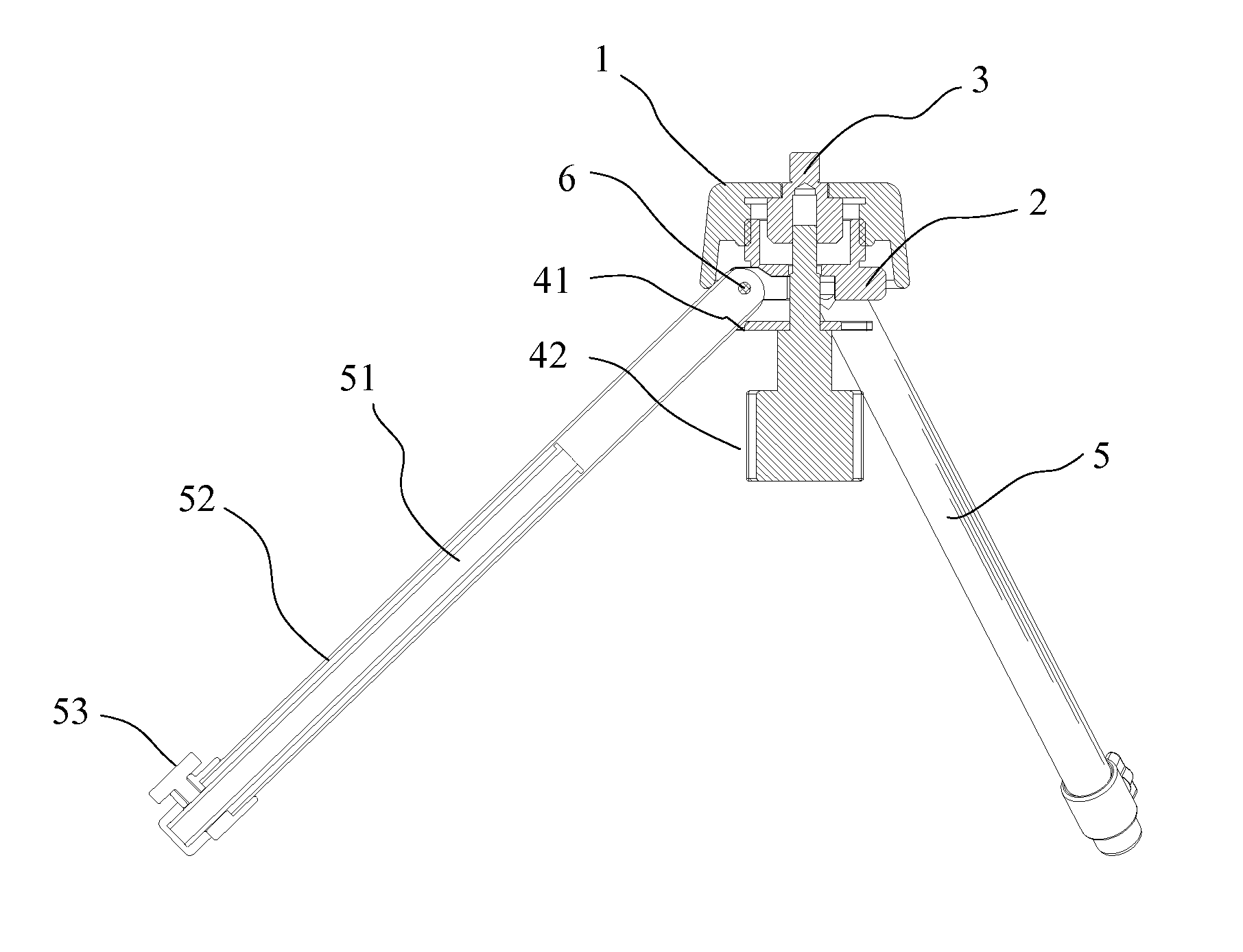
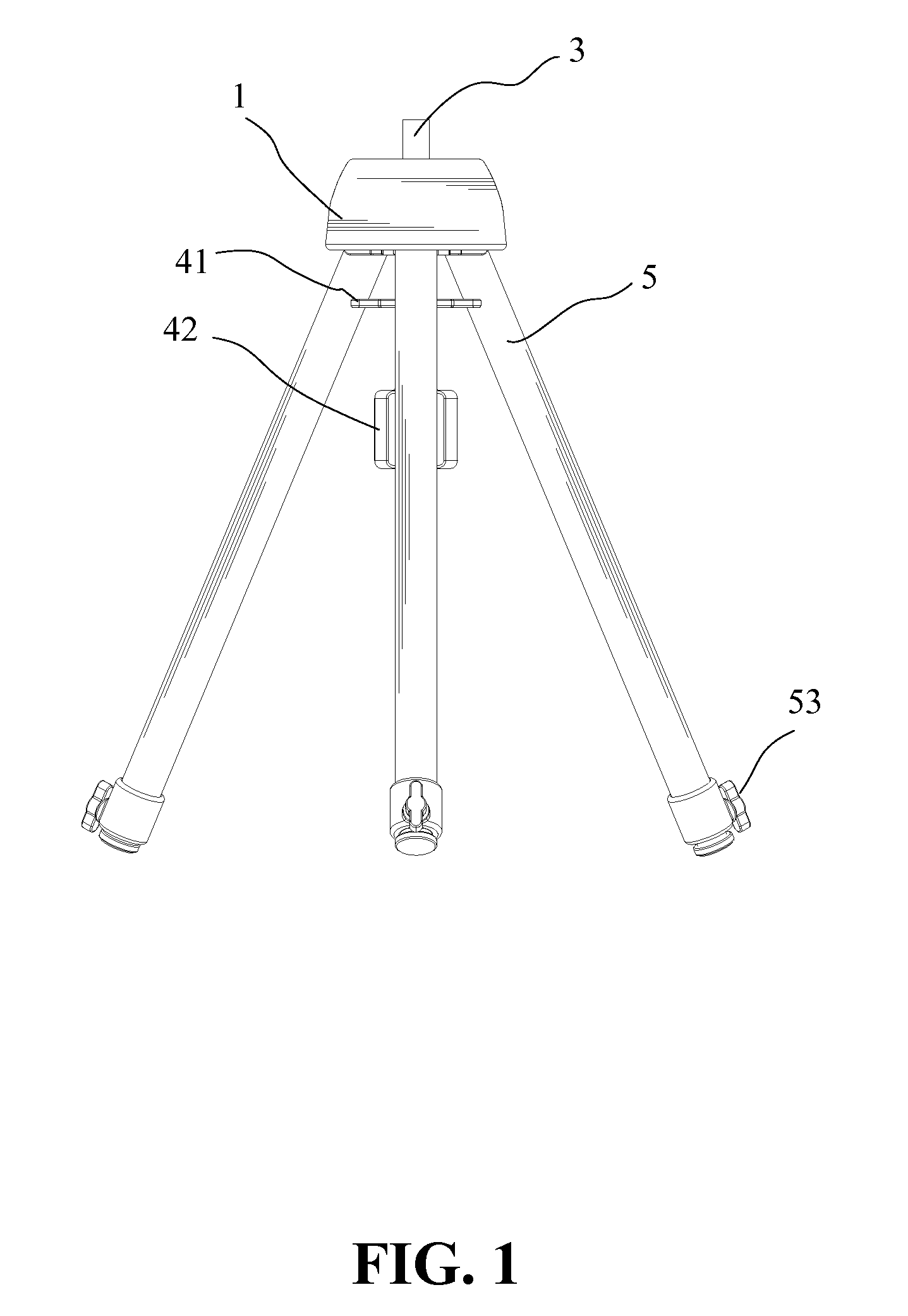
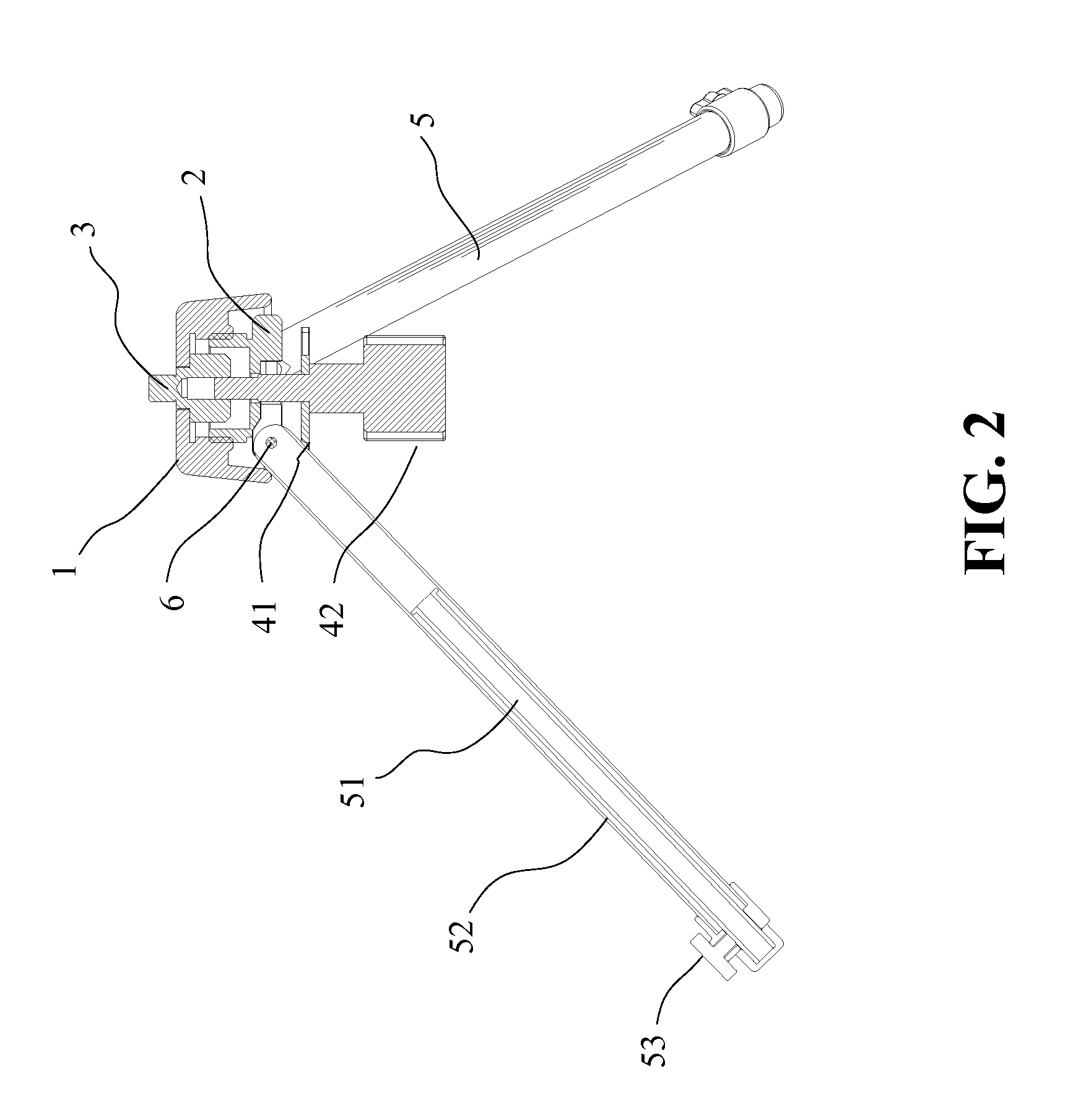
[0043]Referring to FIGS. 1-3, the continuously angle-adjustable multifunction tripod according to the first embodiment of the present invention includes a connecting head 3, a connecting base 2, three legs 5, an adjusting cap 1, a support plate 41, and a bolt member 42. The connecting head 3 has an upper end connecting to a tripod head. The connecting base 2 is disposed in the adjusting cap 1. The inner wall of the adjusting cap 1 and an upper portion of the connecting base 2 are engaged by a thread structure having a certain length. The upper portion of the connecting base 2 is cylinder shaped with an opening at the upper end. The lower end of the connecting base 2 is configured wit...


PUM


Abstract

A continuously angle-adjustable multifunction tripod is provided. The continuously angle-adjustable multifunction tripod includes a connecting base, at least three legs, an adjusting cap, and a supporter. The adjusting cap and the supporter are disposed on and under the connecting base, respectively. Each of the legs is peripherally distributed around the supporter. Upper ends of the legs are movably connected to the connecting base. Distances between the adjusting cap, the connecting base and the supporter are adjustable along a vertical direction, and can be relatively fixed at anywhere therebetween. Meanwhile, a bottom of the adjusting cap and the supporter clamp and fix the legs, so that an angle of each of the legs relative to the horizontal plane can be arbitrarily adjusted in a range from 0° to 90° in accordance with variations of relative positions of the adjusting cap, the connecting base, and the supporter. The present invention has a simple and compact structure, small volume, light weight, low cost, and convenient to operate. Spans of the legs may be arbitrarily adjusted in a range from 0° to 180°, so that the tripod may be mounted quick and steadily in all kinds of complex environments. The present invention may be widely applied in areas of observation, photography, and illuminating, etc.

Description

BACKGROUND OF THE INVENTION[0001]1. Field of the Invention[0002]The present invention relates generally to a tripod for supporting an instrument, such as a telescope, a camera, a camcorder or a measuring instrument, and more particularly, to a continuously angle-adjustable multifunction tripod.[0003]2. The Prior Arts[0004]A tripod is a device operated in accordance with the principle that a plane can be determined by three non-collinear points. A tripod is usually used for supporting a measuring instrument, a camcorder, an illuminating apparatus, or a laboratory appliance. A typical tripod is often provided with three legs designed to be extractable and retractable in order to adjust a supporting height, so that the instrument supported thereupon can be steadily operated at a certain height. Nowadays, tripods are more widely used, and therefore more functions and requirements are desired from tripods. For example, for observation equipment, such as an astronomical telescope, during ...

Claims


Application Information

Patent Timeline
Patent Type & Authority Patents(United States)
IPC IPC(8): F16M11/02
CPCF16M11/32F16M11/36F16M11/16
Inventor SHEN, DAR TSON
Owner SUZHOU SYNTA OPTICAL TECH
Why Eureka
Try Eureka