
Turbine blade with trailing edge root slot

a technology of turbine blades and root slots, which is applied in the field of turbine blades, can solve the problems of reducing the efficiency of a damaged part, not addressing all the problems associated with exposure to working fluid, and the engine cannot operate, so as to achieve the effect of reducing the high stress

Inactive Publication Date: 2011-11-01
FLORIDA TURBINE TECH
View PDF3 Cites 37 Cited by
  • Summary
  • Abstract
  • Description
  • Claims
  • Application Information

AI Technical Summary

Benefits of technology

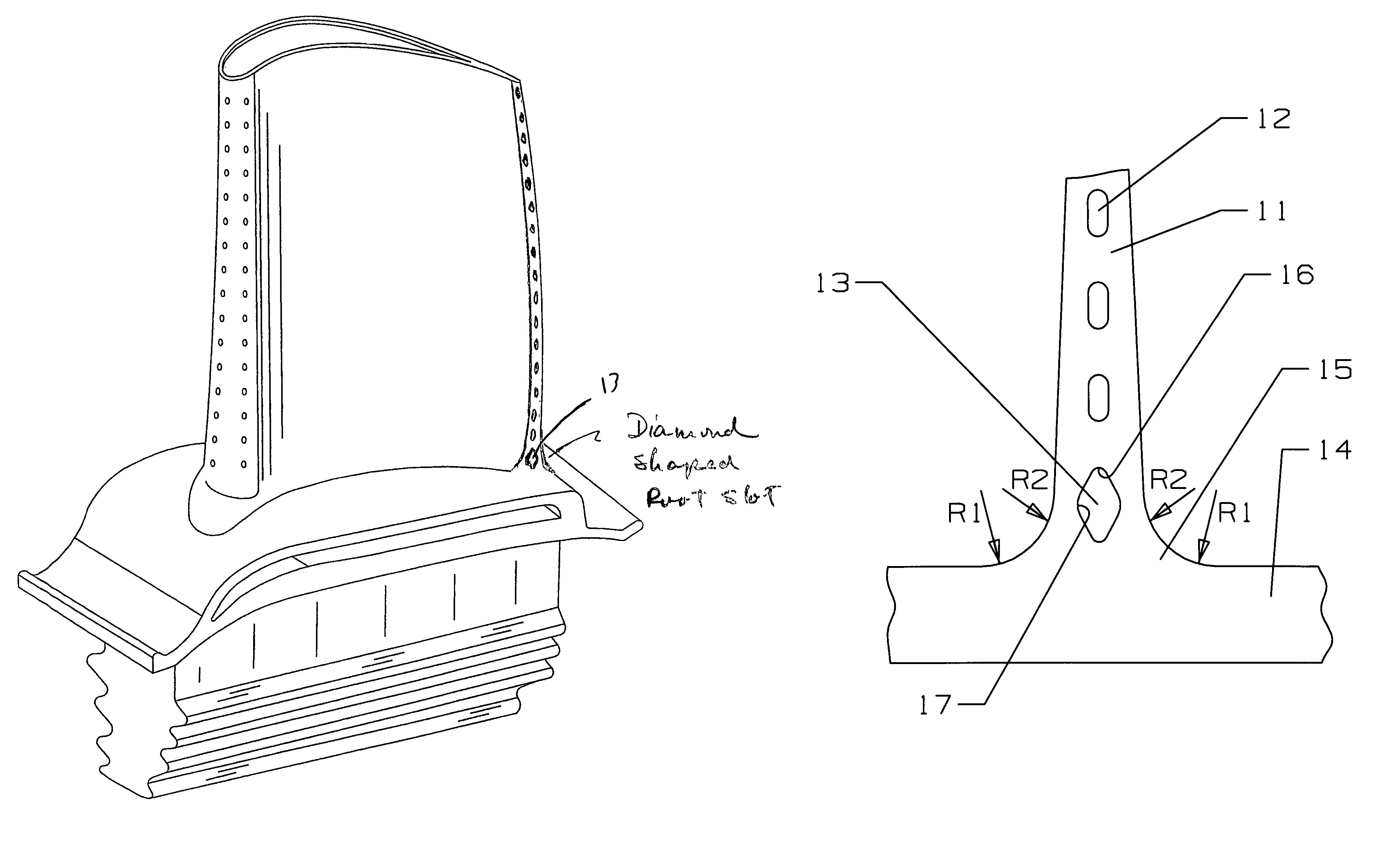
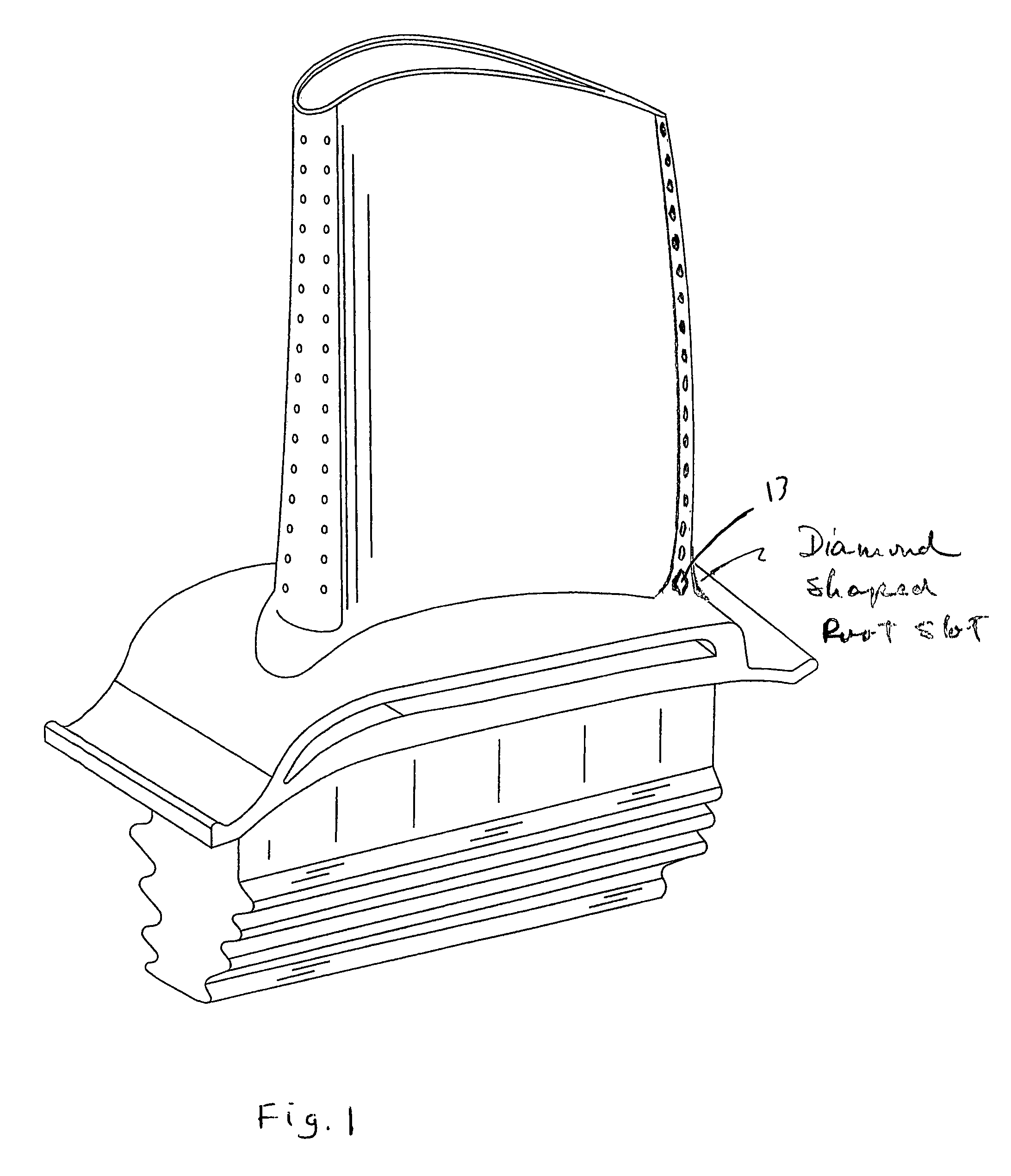
[0011]A turbine rotor blade for use in an industrial gas turbine engine in which the blade includes a root section with a fillet region formed between the root and the platform of the blade. The platform region includes a diamond shaped root slot to discharge cooling air from the internal cooling passage out through the trailing edge of the blade. The diamond shaped cooling slot of the present invention comprises a smaller radius at the upper and lower corners and a much larger radius at the mid section of the slot. The cooling slot is positioned in the trailing edge root section where the upper corner is positioned above the fillet run out location. The diamond shaped cooling slot thus minimizes the high stresses induced by the stress concentration from the cooling slot and the fillet run out location.

Problems solved by technology

When a turbine part is damaged from thermal or stress degradation, the engine cannot operate for a long period of time or the efficiency is decreased from a damaged part.
While robust architecture and thermal barrier coatings help the blades and vanes withstand external thermal and mechanical loads, they do not address all of the issues associated with exposure to the working fluid.
For example, non-uniform temperature distribution between the cooled airfoil portions and relatively hot shroud portions introduces thermal gradients that produce internal thermal stresses.
Cooling channel exits also produce localized thermal stresses, by inducing thermal gradients in the areas immediately surrounding the exits, as a result of sharp drops in temperature.
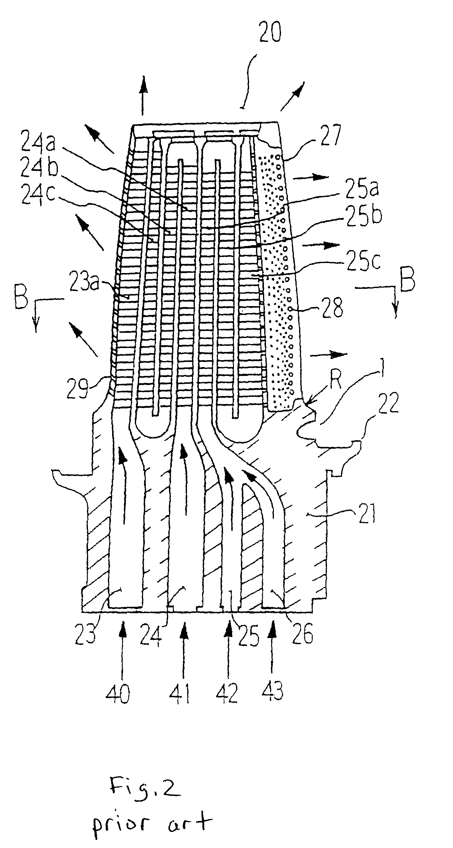
As a result, it becomes impossible to sufficiently suppress the thermal stress with only the base portion structure shaped in the form of the above mentioned fillet ellipse portion R, and cracks develop more frequently in the base portion where large thermal stress is induced.
Also, due to the different effectiveness level of cooling mechanism used for the blade and platform and to the mass distribution between the blade and the platform, the thermally induced strain during transient cycle becomes much more severe.
As a result of this approach, the blade root section wall thickness must be increased which lowers the effectiveness of the trailing edge root section cooling slot.

Method used


Image

  • Turbine blade with trailing edge root slot
  • Turbine blade with trailing edge root slot
  • Turbine blade with trailing edge root slot

Examples


Embodiment Construction

[0016]The present invention is disclosed as a turbine rotor blade for use in an industrial gas turbine engine first stage. However, the diamond shaped cooling slot of the present invention could be used in a stator vane or in an aero engine.

[0017]FIG. 4 shows a rear view of the turbine rotor blade of the present invention with a diamond shaped cooling slot 13. The turbine blade includes a trailing edge 11 with a row of trailing edge cooling holes 12 extending from near the blade tip toward the platform 14 of the blade. These cooling holes 12 are connected to the internal cooling supply passages that pass through the blade such as a serpentine flow cooling circuit. A fillet region 15 is formed between the airfoil portion of the blade and the platform 14 as is well known in the prior art. A compound fillet radii is used as disclosed in the prior art Mazzola wet al U.S. Pat. No. 6,851,924 B2 described above. The compound radii include a first radius R1 and a second Radius R2. However, ...


PUM


Abstract

A turbine rotor blade for use in an industrial gas turbine engine in which the blade includes a root section with a fillet region formed between the root and the platform of the blade. The platform region includes a diamond shaped root slot to discharge cooling air from the internal cooling passage out through the trailing edge of the blade. The diamond shaped cooling slot of the present invention comprises a smaller radius at the upper and lower corners and a much larger radius at the mid section of the slot. The cooling slot is positioned in the trailing edge root section where the upper corner is positioned above the fillet run out location. The diamond shaped cooling slot thus minimizes the high stresses induced by the stress concentration from the cooling slot and the fillet run out location.

Description

BACKGROUND OF THE INVENTION[0001]1. Field of the Invention[0002]The present invention relates generally to a turbine blade in a gas turbine engine, and more specifically to cooling of the fillet along the trailing edge of the turbine blade.[0003]2. Description of the Related Art including information disclosed under 37 CFR 1.97 and 1.98[0004]In an industrial gas turbine engine, the hot gas flow developed within the combustor is passed through a multiple staged turbine to convert the hot gas flow into mechanical energy by rotating the shaft of the engine. It is well known, in the art of gas turbine engines, that the engine efficiency can be increased by providing for a higher gas flow temperature entering the turbine. However, the highest temperature that can be passed into the turbine is depended upon by the material properties and the cooling effectiveness of the first stage stator vanes and rotor blades, since these airfoils are exposed to the highest temperature flow.[0005]Also i...

Claims


Application Information

Patent Timeline
IPC IPC(8): F01D5/08
CPCF01D5/187F05D2250/185F05D2260/941F05D2250/70
Inventor LIANG, GEORGE
Owner FLORIDA TURBINE TECH
Learn More