Continuously variable displacement vane pump and system

a vane pump and continuous variable technology, applied in the direction of machines/engines, positive displacement liquid engines, liquid fuel engines, etc., can solve the problems of significant energy loss, nonlinear relationship between the variation in the output of the pump and the variation of the lubrication requirements of the mechanical system, and significant energy loss

Active Publication Date: 2011-11-01
HANON SYST EFP CANADA LTD
View PDF19 Cites 36 Cited by
  • Summary
  • Abstract
  • Description
  • Claims
  • Application Information

AI Technical Summary

Problems solved by technology

While the lubrication requirements of the mechanical system also vary with the operating speed of the mechanical system, unfortunately the relationship between the variation in the output of the pump and the variation of the lubrication requirements of the mechanical system is generally nonlinear.
In some operating conditions such as low oil temperatures, the overproduction of pressurized lubricating oil can be 500% of the mechanical system's needs so, while such systems work reasonably well, they do result in a significant energy loss as energy is used to pressurize the unneeded lubricating oil which is then “wasted” through the relief valve.
While such variable displacement pumps provide some improvements in energy efficiency over fixed displacement pumps, they still result in a significant energy loss as their displacement is controlled, directly or indirectly, by the output pressure of the pump which changes with the operating speed of the mechanical system, rather than with the changing requirements of the lubrication system.

Method used


Image

  • Continuously variable displacement vane pump and system
  • Continuously variable displacement vane pump and system
  • Continuously variable displacement vane pump and system

Examples


Embodiment Construction

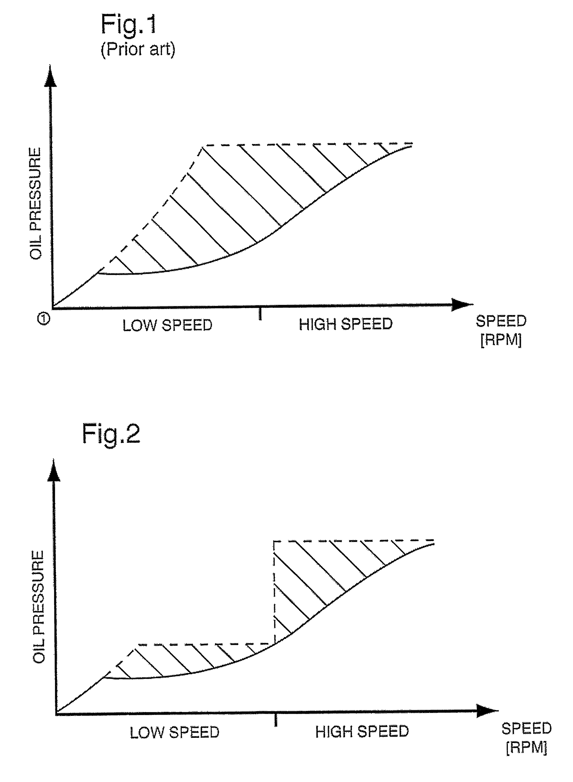
[0018]FIG. 1 shows a typical plot of the lubricating oil pressure requirement (shown in solid line) of a mechanical system, such as a typical internal combustion engine, versus the output (shown in dashed line) of a prior art variable displacement pump, such as the pump taught in the above-mentioned Schuster patent. The corner on the output (dashed line) results from the movement of the control slide by the control piston to reduce the displacement of the pump as the output of the pump reaches a preset value. The shaded area between the engine demand curve and the pump output curve represents the engine operating conditions wherein energy is lost as the pump pressure output exceeds engine demand.

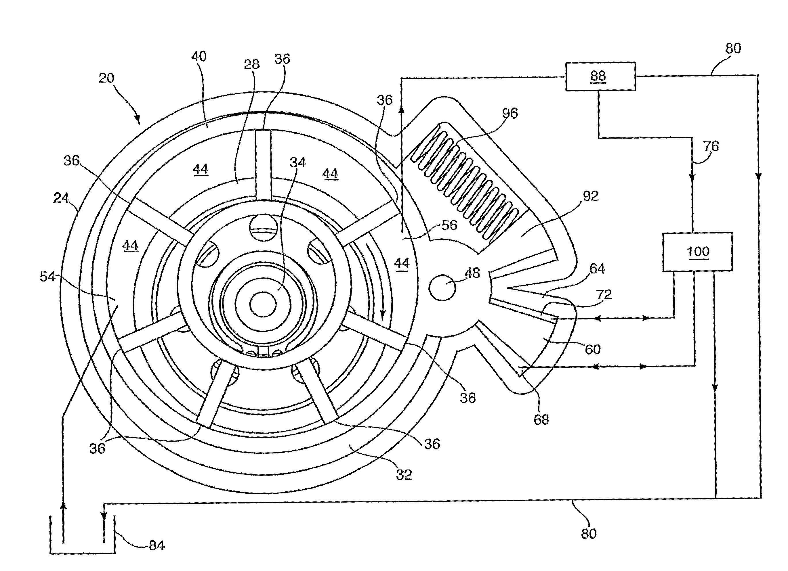
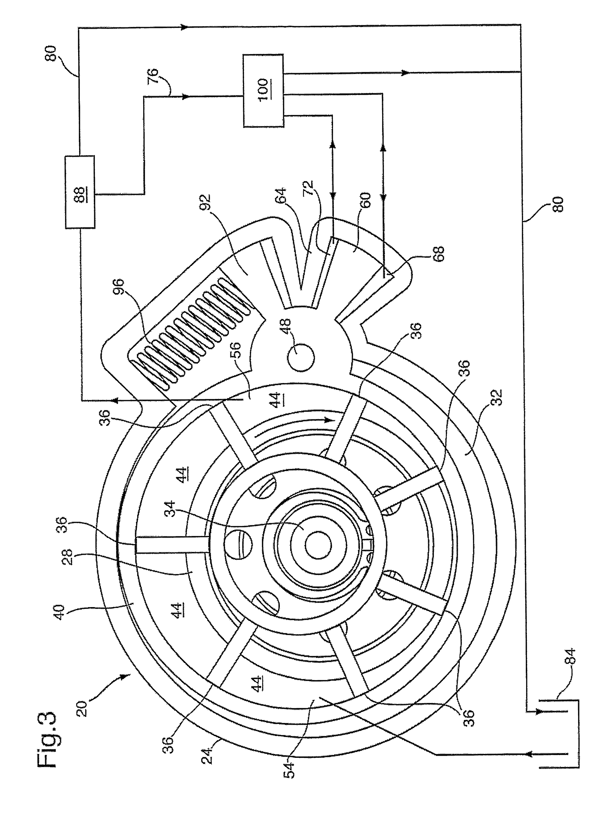
[0019]More recently, a variable displacement vane pump has been developed, as described in co-pending U.S. Provisional Patent Application 60 / 763,720, entitled, “Variable Displacement Variable Pressure Vane Pump System”, filed Jan. 31, 2006 and assigned to the assignee of the present inventio...


PUM


Abstract

A vane pump (20) is provided which has an output pressure hat can be selected from a continuous range of pressures, independent of the operating speed of the pump. The pump has first (68) and second (72) control chambers which create opposed forces on the pump control ring (40) to selectively move the pump control ring (40) between maximum displacement and minimum displacement positions. In one embodiment, the control chamber (68) which urges the ump control ring to the minimum displacement position is continually supplied with pressurized working fluid during operation of the ump while the control chamber (72) which urges the pump control ring to the maximum displacement position can selectively be supplied with pressurized working fluid, isolated, or can be relieved of pressurized working fluid to alter the displacement of the pump.

Description

FIELD OF THE INVENTION[0001]The present invention relates to variable displacement vane pumps. More specifically, the present invention relates to a variable displacement vane pump and system whose output pressure is continuously variable and which can be selected independent of the operating speed of the pump.BACKGROUND OF THE INVENTION[0002]Mechanical systems, such as internal combustion engines and automatic transmissions, typically include a lubrication pump to provide lubricating oil, under pressure, to many of the moving components and / or subsystems of the mechanical systems. In most cases, the lubrication pump is driven by a mechanical linkage to the mechanical system and thus the operating speed, and output, of the pump varies with the operating speed of the mechanical system. While the lubrication requirements of the mechanical system also vary with the operating speed of the mechanical system, unfortunately the relationship between the variation in the output of the pump a...

Claims


Application Information

Patent Timeline
Patent Type & Authority Patents(United States)
IPC IPC(8): F04C2/00F04C14/18
CPCF01M1/16F04C14/223F04C2/3442
Inventor SHULVER, DAVID R.CIOC, ADRIAN C.
Owner HANON SYST EFP CANADA LTD
Why Eureka
Try Eureka