Mounting arrangement for an electric supply cable having a connector with a sealing ring and locking means

a technology of mounting arrangement and electric supply cable, which is applied in the direction of mechanical equipment, machine/engine, coupling device connection, etc., can solve the problems of unusable short circuit and electric contact, and achieve the effect of simple construction and high degree of protection

Inactive Publication Date: 2011-11-01
WHIRPOOL SA
View PDF11 Cites 5 Cited by
  • Summary
  • Abstract
  • Description
  • Claims
  • Application Information

AI Technical Summary

Benefits of technology

[0006]It is an object of the present invention to provide a mounting arrangement for an electric supply cable in a refrigeration compressor of the type described above, with a simple construction and which guarantees not only an electrically and mechanically safe retention of the connector to the shell, but also a high degree of protection for the electric contact elements against humidity.
[0007]Another object of the present solution is to provide a mounting arrangement such as cited above and which allows a safe mechanical retention of the electric supply cable to the connector body, in a positioning orthogonal to the axial direction of the energizing pins, reducing the space required for accommodating said electric supply cable in the mounting place of the compressor.SUMMARY OF THE INVENTION

Problems solved by technology

Since the parts involved in the desired mounting coupling are rigid or substantially rigid, any dimensional deviation will cause the connector to remain electrically coupled to the energizing pins, but in a position in which it is not adequately pressed against the shell of the compressor, making this mounting susceptible to vibrations during the operation of the compressor and also permitting humidity to penetrate between the connector and the shell, towards the energizing pins, with potential risks of causing undesirable short circuits and electric contacts.
Another negative aspect of the known mounting arrangements results from the fact that the connectors do not define a means that can provide an adequate and safe mechanical retention of the electric supply cable in the connector body.

Method used


Image

  • Mounting arrangement for an electric supply cable having a connector with a sealing ring and locking means
  • Mounting arrangement for an electric supply cable having a connector with a sealing ring and locking means
  • Mounting arrangement for an electric supply cable having a connector with a sealing ring and locking means

Examples


Embodiment Construction

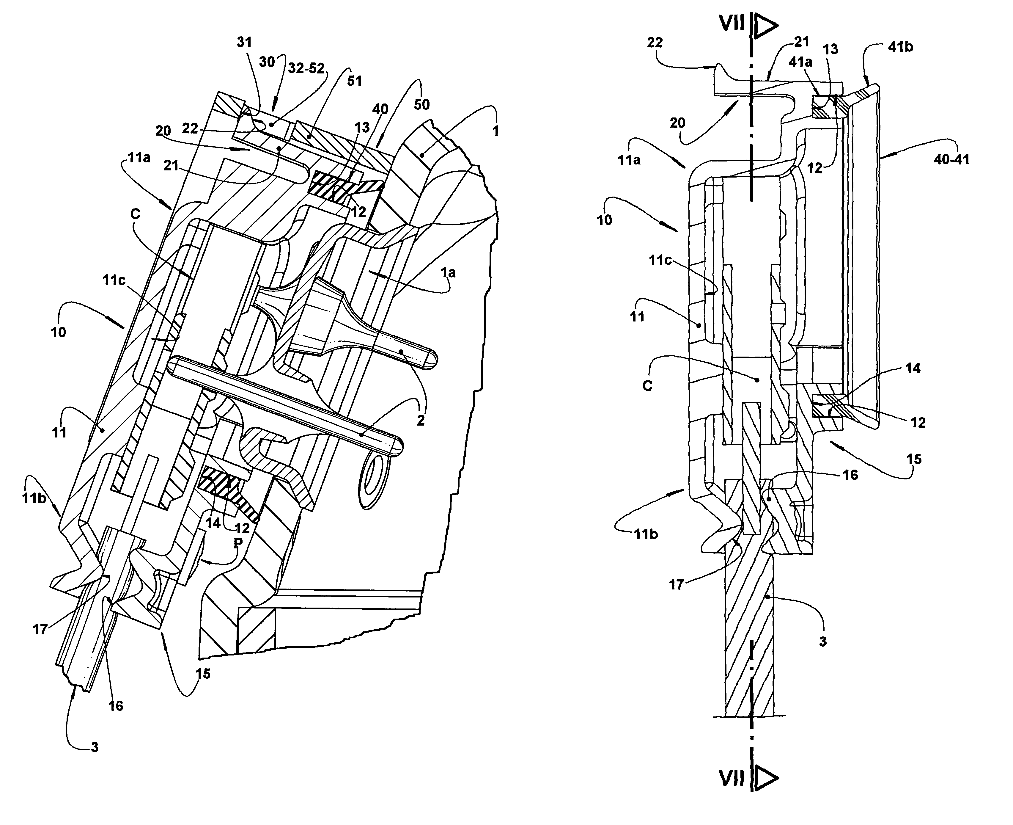
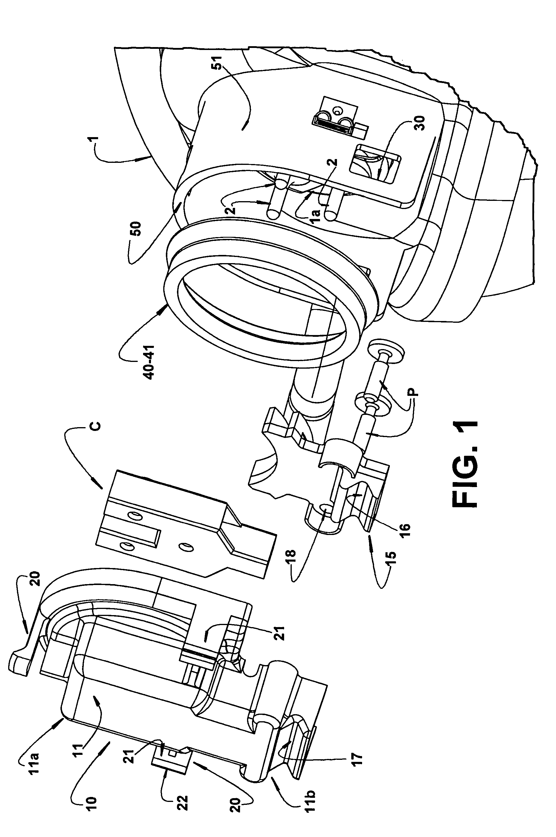
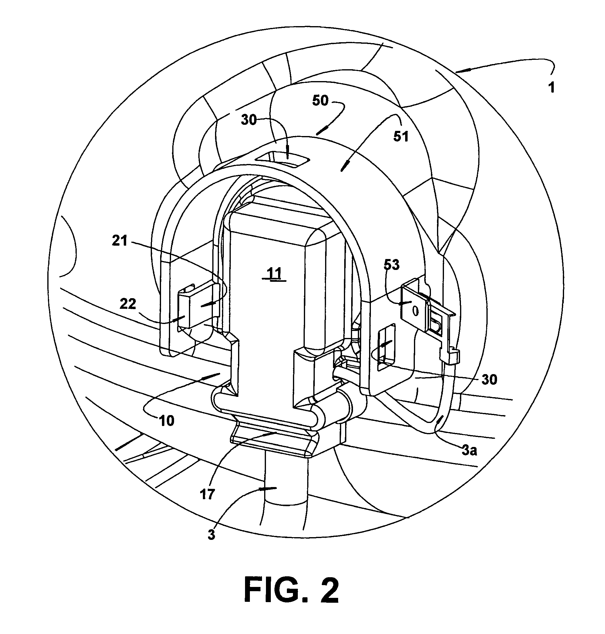
[0020]The present invention refers to a mounting arrangement for an electric supply cable in a refrigeration compressor comprising, in the interior of a hermetic shell 1, an electric motor (not illustrated), electrically coupled to a hermetic terminal 1a including generally three energizing pins 2 carried by the shell 1, outwardly projecting from the latter, and through which said electric motor is energized from an electric power source external to the compressor (not illustrated). The compressor is coupled to the electric power source by means of an electric supply cable 3, having an end provided with electric terminals 4 of adequate construction and to be coupled to the hermetic terminal 1a of the shell 1 of the compressor, and another end (not illustrated) electrically coupled to said electric power source.

[0021]The electric supply cable 3 is coupled to the hermetic terminal 1a in the shell 1 of the compressor, through a connector 10, to be mounted to the shell 1 and having a no...


PUM


Abstract

The mounting arrangement is applied to a refrigeration compressor having a shell (1) externally carrying energizing pins (2) and comprises: a connector (10) to be mounted to the shell (1) and having a non-electric conducting base body (11) which houses and retains electric terminals (4) attached to an electric supply cable (3) and which are designed to fit said energizing pins (2), one of the parts of shell (1) and base body (11) of the connector (10) carrying locking means (20) to be engaged to respective locking receiving means (30) provided in the other part, when the connector (11) is mounted to the shell (1); and an elastic sealing means (40) carried by one of the parts of shell (1) and connector (11) and to be pressed between said parts, around the energizing pins (2), when the connector (11) is mounted to the shell (1).

Description

FIELD OF THE INVENTION[0001]The present invention refers to a mounting arrangement for attaching an electric supply cable in a hermetic refrigeration compressor, of the type which comprises a shell carrying outer energizing pins, said cable being operatively associated with a connector to be mounted to the shell and having a base body, housing electric terminals attached to the electric supply cable and which are designed to be fitted in said energizing pins.BACKGROUND OF THE INVENTION[0002]Refrigeration compressors present, mounted in the hermetic shell thereof, a hermetic terminal having energizing pins externally projecting from the shell and to which is coupled a cable to supply electric energy to the compressor motor housed in the interior of the hermetic shell, said electric supply cable being connected to an electric power source external to the compressor.[0003]In a known solution, the electric supply cable is mounted to the hermetic terminal, by means of electric terminals,...

Claims


Application Information

Patent Timeline
Patent Type & Authority Patents(United States)
IPC IPC(8): H01R13/52H01R13/40
CPCH01R13/5219H01R13/6273H01R13/73H01R24/20H01R2103/00F04C2240/803
Inventor LILIE, DIETMAR ERICH BERNHARDHILLE, CLAUDIO ROBERTOSCHEUER, ILARIO JOSEBORTOLI, MARCOS GIOVANIKRUEGER, MANFREDHUELSE, EMILIO RODRIGUES
Owner WHIRPOOL SA
Why Eureka
Try Eureka