Spectrophotometer

a spectrophotometer and liquid sample technology, applied in the field of spectrophotometers, can solve the problems of inability to use the cuvette cell as previously described, and inability to analyze such a small amount of liquid sample, etc., to achieve easy cleaning operation, simple operation regarding analysis, and low cost

Active Publication Date: 2011-11-01
SHIMADZU CORP
View PDF11 Cites 17 Cited by
  • Summary
  • Abstract
  • Description
  • Claims
  • Application Information

AI Technical Summary

Benefits of technology

[0020]With the spectrophotometer according to the present invention, a liquid sample held in the sample holding unit can be a very small amount of approximately 1 through 2 μL or less than that. Therefore, it is preferable for the analysis of a trace liquid sample such as a biological sample. In addition, the preparation of the sample merely requires dropping a liquid sample onto the upper surface of the sample stage. Hence, the operation regarding the analysis is very simple and consumes little time. Furthermore, the portions touched by the liquid sample are flat: such as the upper surface of the sample stage, lower surface of the window plate or other portions. Therefore, it is easy to perform a cleaning operation by wiping and washing with cleaning fluid. Also, it is easily dryable.
[0021]Unlike the previously described configuration in which a liquid sample is held between the end surfaces of optical fibers, a liquid sample does not touch the main body of the apparatus such as a measurement optical system. Therefore, scratches and contaminations of the main body of the expensive apparatus can be prevented, which controls the maintenance cost. In addition, since the body of the optical system which constitutes the measurement optical path is not required to be displaced in setting or changing samples, the measurement optical path can be kept fixed, which is also effective in simplifying the structure and decreasing the cost. As a matter of course, adjusting operation of the optical axis between the light-delivering optical fiber and the light-receiving optical fiber is not necessary. Therefore, there is no risk of light quantity loss due to the disagreement of the optical axes. Furthermore, the sample change operation is easy either by manual or automatic operation, which enables the enhancement in the throughput of the analysis.
[0022]In the spectrophotometer according to the present invention, as previously described, the distance between the sample stage's upper surface and the window plate's lower surface forms the measurement optical path length. Therefore, the setting accuracy of the distance needs to be enhanced in order to perform an accurate measurement. Given this factor, as an embodiment of the present invention, the bodies of the sample stage and the window plate, or a member holding each of the sample stage and the window plate is made to touch a regulatory member disposed in the space between the sample stage and the window plate in order to set a distance between the upper surface of the sample stage and the lower surface of the window plate to be the predetermined distance.
[0023]In this configuration, after the liquid sample is dropped onto the upper surface of the sample stage, the distance between the window plate and the sample stage is gradually reduced. When the bodies of the sample stage and the window plate touch or the member that holds them touches the regulatory member, the narrowing operation is halted. In this manner, the aforementioned distance can be accurately set. This accomplishes an accurate determination of the measurement optical path length and the measurement accuracy is increased. Simultaneously, the configuration is simple and a high positional accuracy is not required in the stopping operation of the moving mechanism for the window plate for example. Therefore, this configuration is also advantageous in reducing the cost.
[0024]Generally, in a transmission measurement, the measurement accuracy can be increased, for example, by decreasing the measurement optical path length if the sample has a high concentration and hence a large absorbance per unit length or increasing the measurement optical path length if the sample has a low concentration and hence a small absorbance per unit length. Given these factors, in the configuration of the aforementioned embodiment, the regulatory member may be changed in height in order to change the predetermined distance. With this configuration, the measurement optical path length can be easily changed. Regardless of such a change, the completely same measurement optical system can be used and a plurality of sample cells having different optical path lengths are not required as with a cuvette cell. Consequently, it is possible to realize the change of the measurement optical path length with a small increase in cost.

Problems solved by technology

In such cases, the quantity of the liquid sample to be analyzed is usually extremely small.
In particular, in a DNA-related analysis, a sample is precious and expensive.
A cuvette cell as previously described cannot be used for the purpose of analyzing such a small amount of liquid sample.
However, even such a capillary cell generally requires a liquid amount of more than a few μL and a liquid sample less than this amount cannot be analyzed.
In addition, a capillary cell has disadvantages in that injecting a liquid sample into the cell is cumbersome and cleaning after a measurement is troublesome.
However, this spectrophotometer has a disadvantage in that a light quantity loss occurs unless the optical axis of the light-delivering optical fiber 41 is coincident with that of the light-receiving optical fiber 43.
In addition, since the optical fibers 41 and 43 constituting the measurement optical system directly contact with the liquid sample S, the sample change operation is far more troublesome and time-consuming compared to the case, for example, of inserting a sample cell in a measurement light path in a sample chamber space or the like as previously described.

Method used


Image

  • Spectrophotometer
  • Spectrophotometer
  • Spectrophotometer

Examples


Embodiment Construction

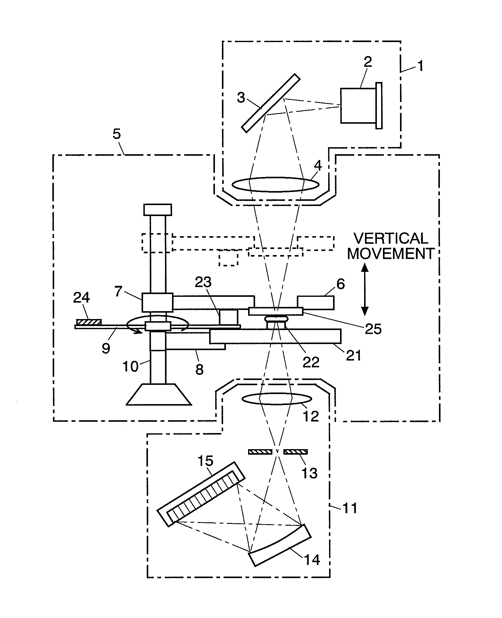
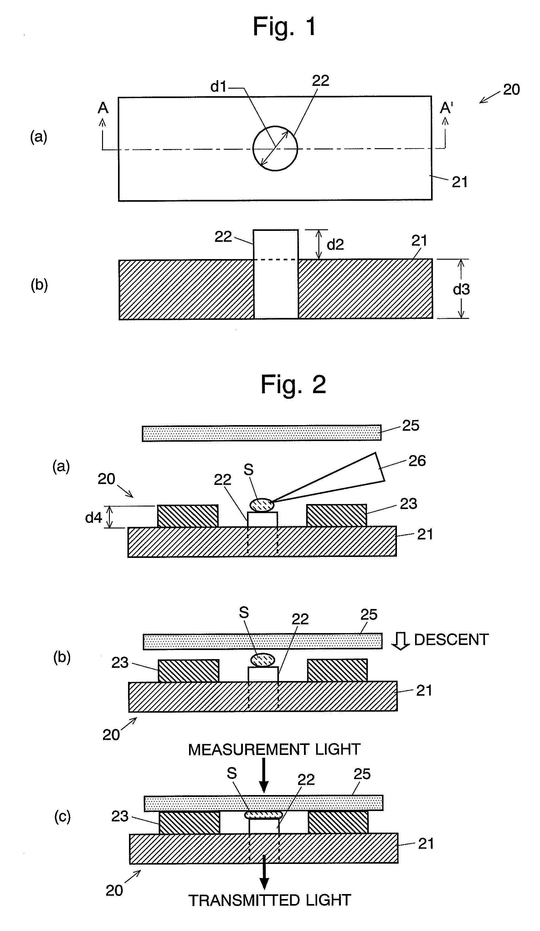
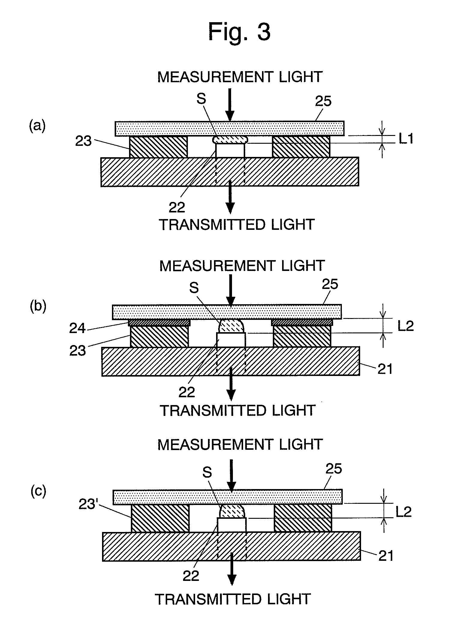
[0064]An embodiment of the spectrophotometer according to the present invention will be described with reference to the figures. First, the characteristic configuration of the sample holding unit which is used in the spectrophotometer of the present embodiment is described. FIG. 1(a) is a top plain view of the pedestal unit of the sample holding unit and FIG. 1(b) is an end view of the same pedestal unit viewed from the arrow A-A′. FIG. 2 is a schematic side view for explaining the procedure of setting a liquid sample in this sample holding unit.

[0065]The sample holding unit is roughly composed of a pedestal unit 20 and a transparent cover plate (i.e. the window plate in the present invention) 25 to be placed thereon. As illustrated in FIG. 1, the pedestal unit 20 is composed of a base plate 21 made of a material such as metal or plastic having a light-blocking property and a cylindrical light-transmitting body (i.e. the sample stage in the present invention) 22 made of a material h...


PUM

PropertyMeasurementUnit
optical path lengthaaaaaaaaaa
diameter d1aaaaaaaaaa

Abstract

A liquid sample is dropped onto the upper surface of a transparent and cylindrical light-transmitting body (22), and the liquid sample is maintained as a droplet by the surface tension. From above the liquid sample, a transparent cover plate (25) is lowered down to the position where the lower surface thereof touches a spacer (23) in order that the liquid sample is held in the small gap formed between the upper surface of the light-transmitting body (22) and the lower surface of the transparent cover plate (25). A measurement light is provided into the liquid sample held in this manner from immediately above it, and passes through the liquid sample. The transmitted light emitted downwards through the light-transmitting body (22) is introduced into a spectro-detecting unit to be spectro-measured. The measurement optical path length can be adjusted by the height of the spacer (23). This enables an easy transmission spectro-measurement of an extremely small amount of liquid sample.

Description

TECHNICAL FIELD[0001]The present invention relates to a spectrophotometer for delivering light onto or into a liquid sample and measuring the transmitted light. More precisely, it relates to a spectrophotometer suitable for measuring the transmission characteristics of a small amount of liquid sample.BACKGROUND ART[0002]A conventional spectrophotometer such as an ultraviolet visible spectrophotometer which has been widely and generally used includes an optical system. In the optical system, for example, a light emitted from a light source is wavelength-dispersed by a spectroscope, a measurement light having a specific wavelength is taken out, the measurement light is delivered onto or into the sample placed in a sample chamber, and the light which has passed through the sample is detected. In the sample chamber, various types of sample cells and sample change mechanisms are placed in accordance with the purpose of analysis, the kind of sample, and other factors (for example, refer t...

Claims


Application Information

Patent Timeline
Patent Type & Authority Patents(United States)
IPC IPC(8): G01J3/02G01N21/27G01J3/28
CPCG01N21/251G01N21/0303G01N2021/035G01N21/31G01N2201/0668
Inventor TSUKUDA, YASUO
Owner SHIMADZU CORP
Why Eureka
Try Eureka