
Navigation and control system for autonomous vehicles

a technology of autonomous vehicles and control systems, applied in the direction of non-vehicle mounted steering controls, process and machine control, navigation instruments, etc., can solve the problems of driver's inability to perform all of these functions, driver's ability to become at risk, driver's disorientation or inability to physically command the vehicle,

Active Publication Date: 2011-11-01
SAMSUNG ELECTRONICS CO LTD
View PDF39 Cites 297 Cited by
  • Summary
  • Abstract
  • Description
  • Claims
  • Application Information

AI Technical Summary

Benefits of technology

Enables precise identification and avoidance of obstacles in real-time, even in challenging conditions, improving safety and operational efficiency of autonomous vehicles by providing accurate three-dimensional mapping and obstacle detection.

Problems solved by technology

Yet, the driver's ability to perform all of these functions can become compromised due to physical factors such as driver fatigue, driver impairment, driver inattention, or other factors such as visibility that reduce the reaction time needed by the driver to successfully avoid hazards.
Furthermore, in environmentally dangerous surroundings such as for example in warfare settings or in settings where toxic or nuclear radiation hazards are present, the driver is at risk.
In other more conventional environments, the driver may become disoriented or incapable of physically commanding the vehicle as would occur if the driver suffered a medical emergency or if for example the driver became disoriented under the driving conditions.
Despite this work, realization of suitable visualization, obstacle identification, and obstacle avoidance systems and methods has not been without problems limiting the operation of vehicles.

Method used


Image

  • Navigation and control system for autonomous vehicles
  • Navigation and control system for autonomous vehicles
  • Navigation and control system for autonomous vehicles

Examples


working example

[0138]A 2005 Ford Escape Hybrid™ (hereinafter referred to as the working vehicle) was modified to include the imaging sensors 8 of the present invention. The working vehicle used a hybrid drive system in which an electric engine operates virtually all of the time and in which the gas engine starts and stops automatically to either provide extra horsepower or to recharge the electric engine's battery. The working vehicle's electrical system, which was powered by a 330-volt battery, provides over 1300 watts of power to the equipment mounted in the working vehicle.

[0139]The working vehicle utilized a commercially available Advanced Electronic Vehicle Interface Technology (AEVIT) “drive-by-wire” system from Electronic Mobility Controls (EMC) to physically control the car. The AEVIT system uses redundant servos and motors to turn the steering wheel, switch gears, apply throttle, and apply brake. This commercial system has a proven safety record in the automobile industry due to its use o...


PUM


Abstract

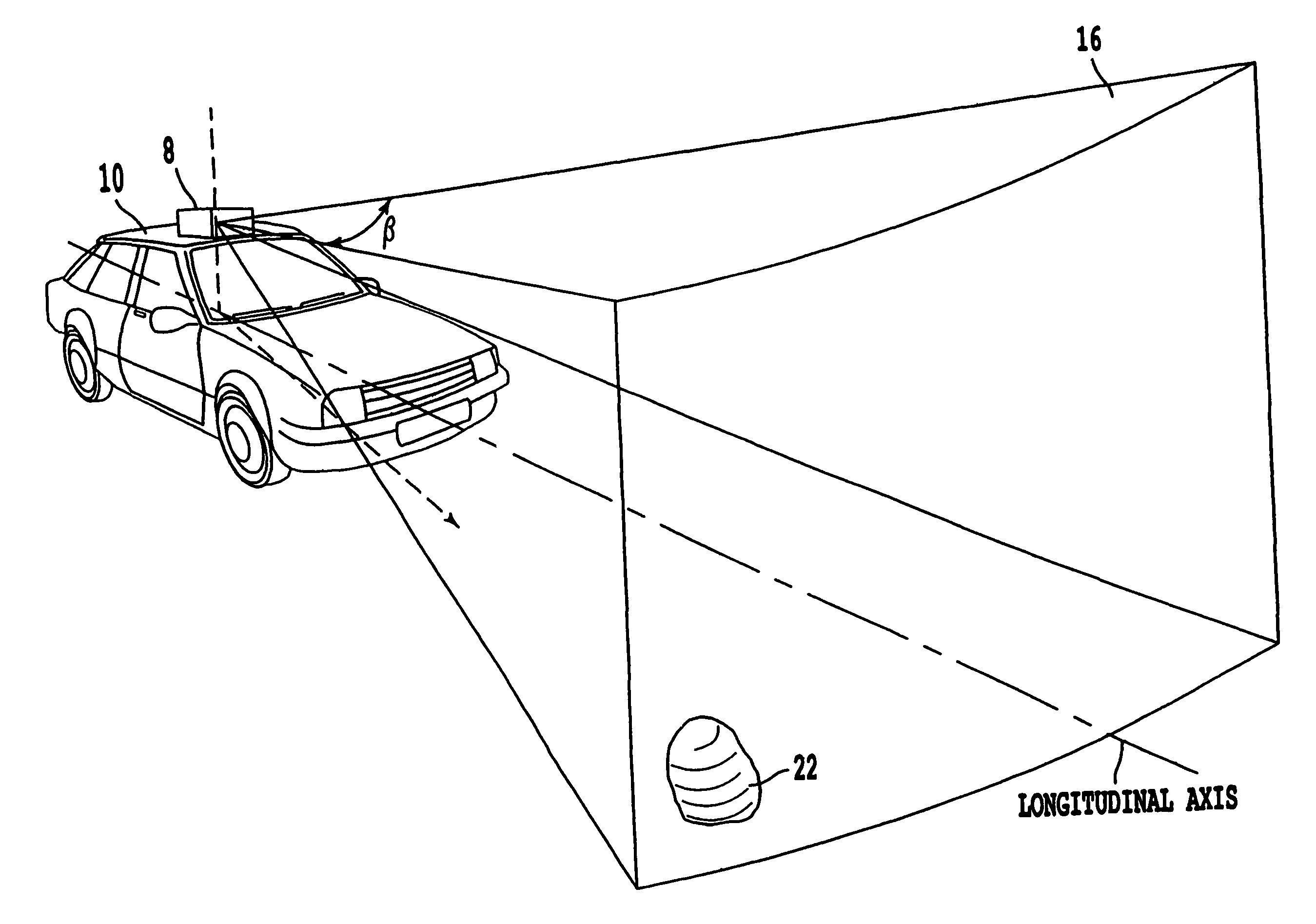
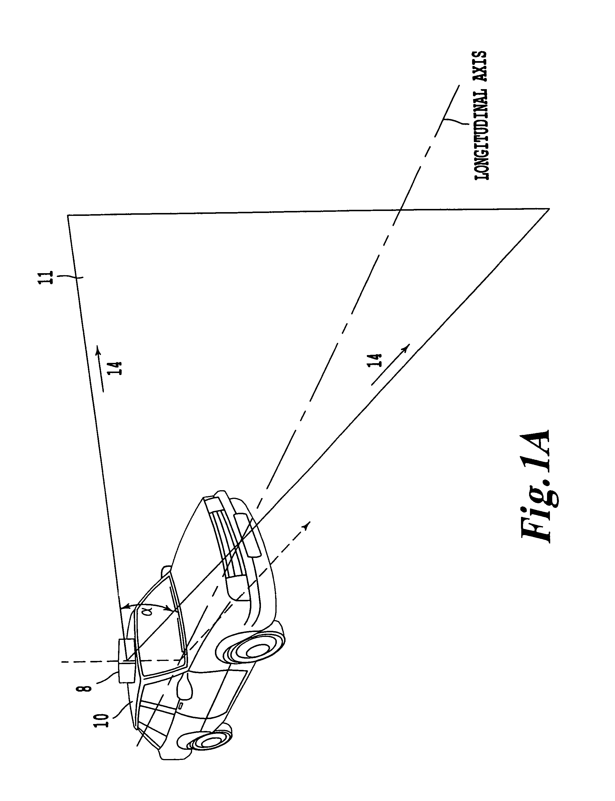
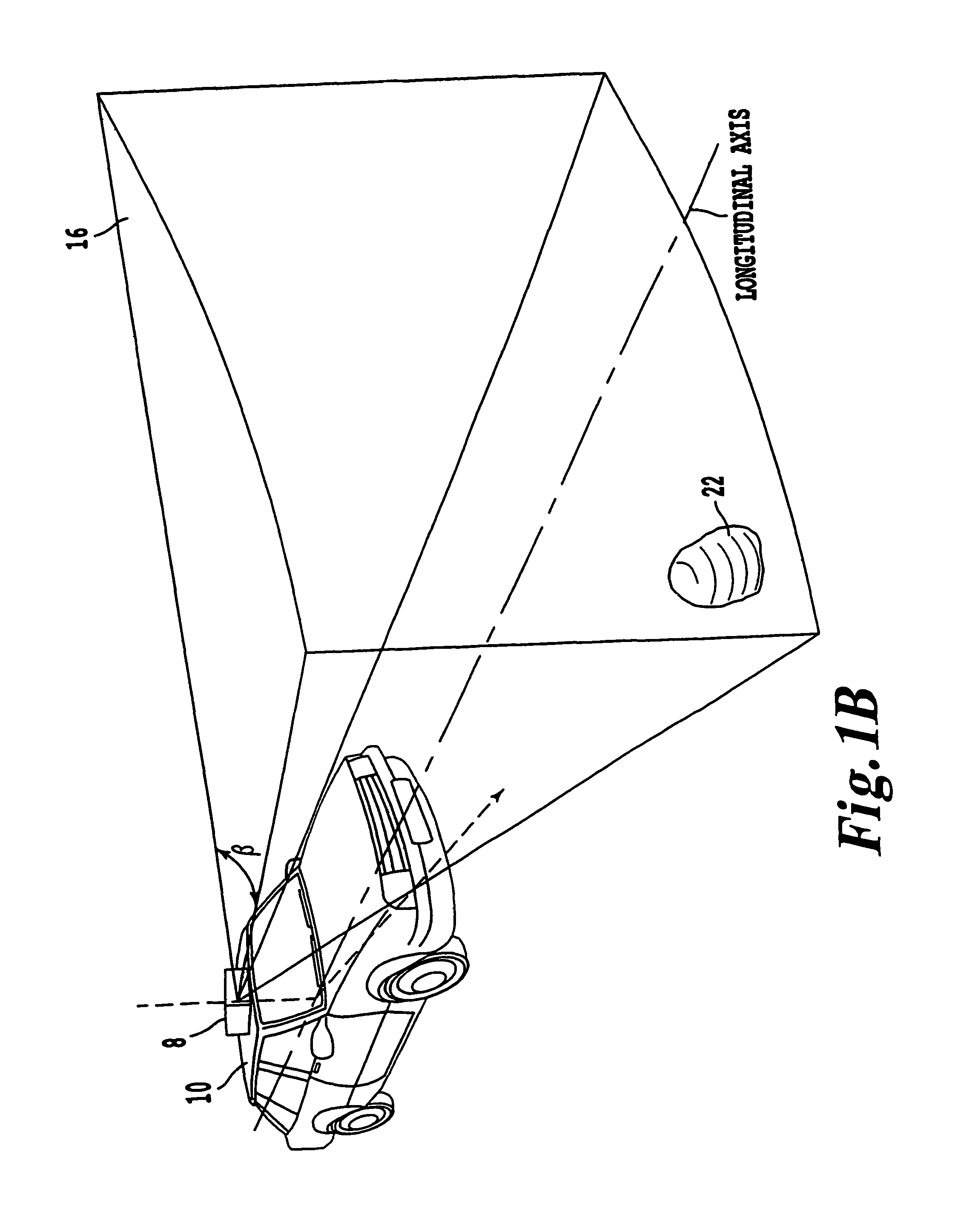
A navigation and control system including a sensor configured to locate objects in a predetermined field of view from a vehicle. The sensor has an emitter configured to repeatedly scan a beam into a two-dimensional sector of a plane defined with respect to a first predetermined axis of the vehicle, and a detector configured to detect a reflection of the emitted beam from one of the objects. The sensor includes a panning mechanism configured to pan the plane in which the beam is scanned about a second predetermined axis to produce a three dimensional field of view. The navigation and control system includes a processor configured to determine the existence and location of the objects in the three dimensional field of view based on a position of the vehicle and a time between an emittance of the beam and a reception of the reflection of the emitted beam from one of the objects.

Description

DISCUSSION OF THE BACKGROUND[0001]1. Field of the Invention[0002]The invention relates to a three-dimensional (3D) imaging sensor and method for controlling an autonomous vehicle.[0003]2. Background of the Invention[0004]In a modern vehicle, the driver remains a critical component of the vehicle's control system as the driver makes numerous decisions directed to the safe operation of the vehicle including speed, steering, obstacle and hazard recognition, and avoidance thereof. Yet, the driver's ability to perform all of these functions can become compromised due to physical factors such as driver fatigue, driver impairment, driver inattention, or other factors such as visibility that reduce the reaction time needed by the driver to successfully avoid hazards.[0005]Furthermore, in environmentally dangerous surroundings such as for example in warfare settings or in settings where toxic or nuclear radiation hazards are present, the driver is at risk. Indeed, roadside bombs in Iraq are ...

Claims


Application Information

Patent Timeline
Patent Type & Authority Patents(United States)
IPC IPC(8): G01C21/00
CPCB60W30/00G05D1/024G05D1/0274G05D1/0278B60W10/06B60W10/20B60W30/095G05D1/00G05D1/0238G05D1/0242G05D2201/0213B60W2550/147G01S7/4817G01S17/931B60W2552/35
Inventor TREPAGNIER, PAUL GERARDNAGEL, JORGE EMILIOKINNEY, POWELL MCVAYDOONER, MATTHEW TAYLORWILSON, BRUCE MACKIESCHNEIDER, JR., CARL REIMERSGOELLER, KEITH BRIAN
Owner SAMSUNG ELECTRONICS CO LTD
Learn More