
Control device for vehicular power transmitting apparatus

a control device and transmission device technology, which is applied in the direction of electric propulsion mounting, machines/engines, instruments, etc., can solve the problems of preventing limiting the operation state of electric motors, and limiting the output torque output of electric motors, so as to reduce the risk of resonance phenomena, the effect of shortening the time and avoiding the occurrence of resonance phenomena

Inactive Publication Date: 2011-11-08
TOYOTA JIDOSHA KK
View PDF29 Cites 12 Cited by
  • Summary
  • Abstract
  • Description
  • Claims
  • Application Information

AI Technical Summary

Benefits of technology

The present invention provides a control device for a vehicular power transmitting apparatus that can quickly decrease the rotation speed of the internal combustion engine to pass through a resonance point, preventing resonance phenomena. This is achieved by limiting the differential state of the electric differential portion by either decreasing the operational state of the electric motor or mechanically limiting the differential state of the electric differential portion. The control device can also limit the differential state of the electric differential portion based on the limitation of the battery charge / discharge or the failure of the electric motor. This allows for a faster decrease in the rotation speed of the internal combustion engine and prevents resonance phenomena.

Problems solved by technology

In a stopping process of the internal combustion engine in a differential manner, when the rotation speed falls within the resonance point, there is a fear of the above-mentioned resonance phenomena being caused.
However, for example, if a charge / discharge of a battery supplying electric power to the motor is limited, the operational state of the electric motor is limited.
If the internal combustion engine is controllably stopped by the electric motor in this state, limitation is imposed on an output torque output from the electric motor, which may lengthen a time period necessary for decreasing the rotation speed of the internal combustion engine.
Thus, in a decreasing process of the rotation speed of the internal combustion engine, there is a fear that longer time period is required to pass through the resonance point, causing resonance phenomena.

Method used


Image

  • Control device for vehicular power transmitting apparatus
  • Control device for vehicular power transmitting apparatus
  • Control device for vehicular power transmitting apparatus

Examples


embodiment 1

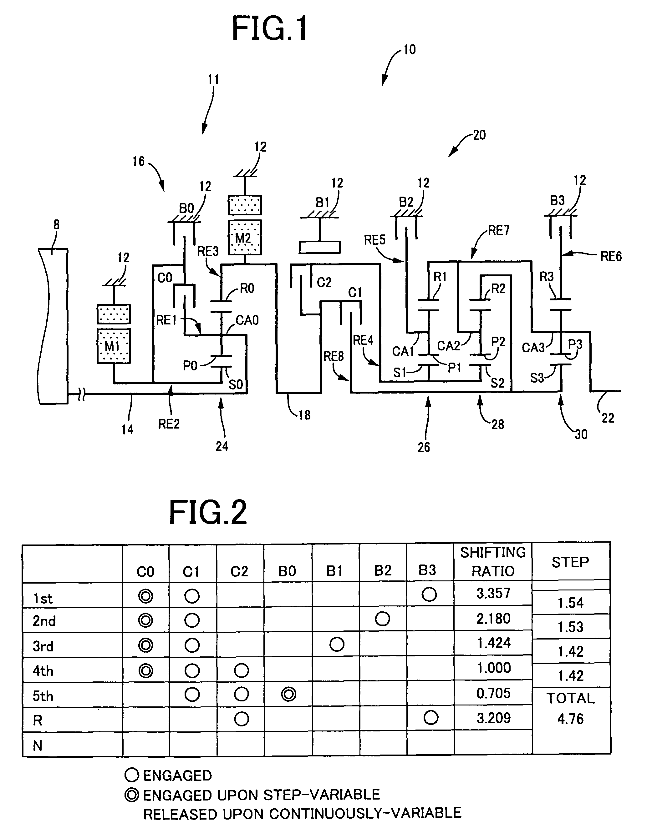
[0027]FIG. 1 is a skeleton view illustrating a shifting mechanism 10, forming part of a power transmitting apparatus for a hybrid vehicle, to which a control device of one embodiment according to the present invention is applied. As shown in FIG. 1, the shifting mechanism 10 includes an input shaft 14 serving as an input rotary member, a differential portion 11 directly connected to the input shaft 14 or indirectly connected thereto through a pulsation absorbing damper (vibration damping device) not shown, an automatic shifting portion 20 connected via a power transmitting member (corresponding to an output shaft of differential mechanism) 18 in series through a power transmitting path between the differential mechanism 11 and drive wheels 38 (see FIG. 6) to serve as a step-variable type transmission, and an output shaft 22 connected to the automatic shifting portion 20 as an output rotary member, all of which are disposed in a transmission casing 12 (hereinafter briefly referred to...

embodiment 2

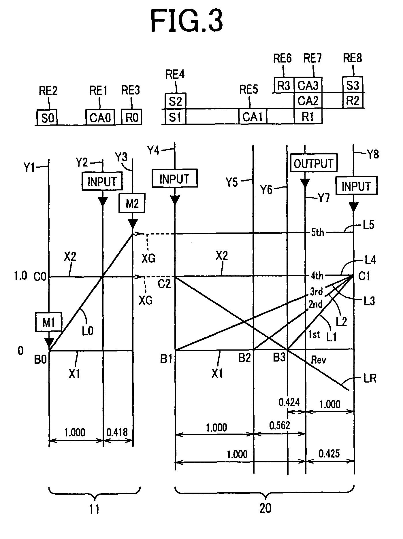
[0148]FIG. 12 is another collinear chart illustrating a relative rotation speed of the rotary elements of the differential portion 11, and explaining a control for decreasing the engine rotation speed NE by the first electric motor M1. In this embodiment, a control operation for stopping the engine 8 performed during the vehicle running at a predetermined vehicle speed V will be explained. Specifically, this control is applied to, for example, a case where the vehicle state is switched from an engine running area shown in FIG. 7 to a motor running area, when the vehicle is running in the engine running mode during the decelerating i.e. slowdown vehicle speed.

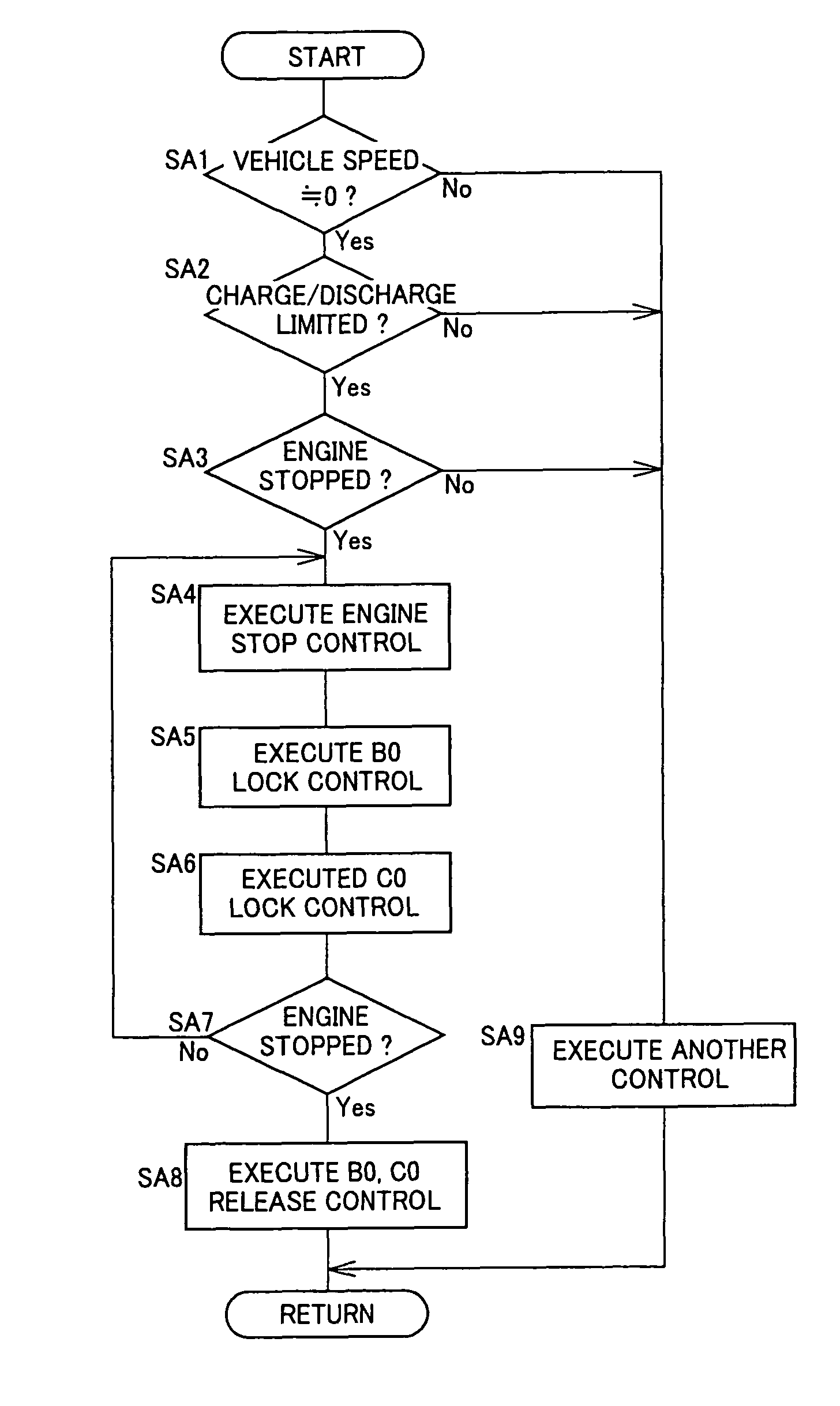
[0149]In this embodiment, the engine stop controlling means 112 allows the switching brake B0 and the switching clutch C0 to be suitably engaged (or semi-engaged) according to a running state, upon control for the engine stopping. Thus, the engine rotation speed NE quickly decreases to pass through the resonance point in the sho...


PUM


Abstract

The present invention provides, in a vehicular power transmitting apparatus including a differential portion electrically controlled, a control device which can quickly decrease the engine rotation speed, even if the operational state of an electric motor is limited. An engine-stop controlling means (112) includes limiting means for limiting the differential state of a differential portion (11) by a switching brake (B0) and a switching clutch (C0) when the operational state of a first electric motor (M1) is limited. Therefore, a torque in a direction for decreasing a rotation speed (NE) of an engine (8) is applied by limiting the differential state of the differential portion (11), for example, in a vehicle stopped state. As a result, the rotation speed (NE) of the engine (8) is quickly decreased to pass through a resonance point in a short time, whereby occurrence of resonance phenomena can be prevented.

Description

TECHNICAL FIELD[0001]This invention relates to a control device for a vehicular power transmitting apparatus. More particularly, it relates to a control technique upon stopping an internal combustion engine, in a vehicular power transmitting apparatus which includes an electric differential device functioning as an electric differential portion by controlling an operational state of an electric motor.BACKGROUND ART[0002]A vehicular power transmitting apparatus including an electrically controlled differential portion is known. In the electrically controlled differential portion, a differential state of rotation speeds between an input shaft to which an internal combustion engine is connected and an output shaft is controlled, by controlling an operational state of an electric motor connected to a rotary element of a differential mechanism in a power transmissive state. For example, a power output device disclosed in Patent Literature 1 (Japanese Patent Publication No. H10-306739) ma...

Claims


Application Information

Patent Timeline
Patent Type & Authority Patents(United States)
IPC IPC(8): B60W10/02B60K6/20B60K6/445B60K6/543B60K6/547B60W10/06B60W10/08B60W10/10B60W10/26B60W20/00F02D29/02
CPCB60K6/445B60W10/02B60W10/08B60W10/115B60W30/18054B60W20/00Y10T477/23B60W2710/0644Y02T10/6239Y10T477/26Y10T477/24Y02T10/62B60K2006/268B60K6/28B60W10/06B60W20/10
Inventor KUMAZAKI, KENTAMATSUBARA, TOORUTABATA, ATSUSHI
Owner TOYOTA JIDOSHA KK
Learn More